GMPC II communication driver is the driver to communicate with power meter GIMAC/GIMACII/GIMACIII/GIPAM-2200 FM(or FZ etc) model of LSIS Co., Ltd. in Korea.
GIPAM-2200 FM model communicate with GMPC controller( GMPC I, GMPC II, GMPC III, GMPC V, ... ) and computer read and write GMPC's data.
Note) Setting of GIPAM-2200 T model
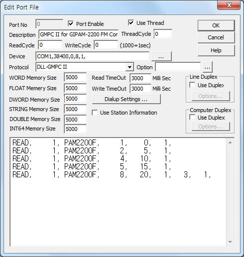
<Figure 1> is read setting example of GMPC II communication driver for GIPAM-2200 FM model.
|
|
| <Figure 1> Read setting example of GMPC II communication driver for GIPAM-2200 FM model |
Device part of <Figure 1> input Com Port(COM1 or TCP/IP, UDP/IP, etc), Baud Rate(38400), Parity Bit(0), Data Bit(8), Stop Bit(1) respectively according to setting of GMPC.
Baud rate, parity bit, data bit, stop bit can set by using switch of rear or front panel(GMPC controller).
GMPC II communication driver read schedule for GIPAM-2200 FM
Read schedule setting parameters are as follows:
1) STATION – GIPAM-2200 FM controller station number = 0 ~ 255.
2) Controller Model – Model = PAM2200F (when using GIPAM-2200 FM model).
3) Read data type – Data type = 0, 1, 2, 3.... ( Cmd - 10h, refer to reference manual of GIPAM-2200 FM )
4) Save Start Address for Communication Server – saveing start address of Communication Server.
5) Read Size – Read size. Fixed according to read data type. ( Refer to <Table 1> ~ <Table 2> )
6) Sub1 command - Input Sub1 command according to controller model.
7) Sub2 command - Input Sub 2 command according to controller model.
Read schedule example)
READ, 1, PAM2200F, 1, 0, 1,
READ, 1, PAM2200F, 2, 5, 1,
READ, 1, PAM2200F, 4, 10, 1,
READ, 1, PAM2200F, 5, 15, 1,
READ, 1, PAM2200F, 8, 20, 1, 3, 1,
<Table 1> is data saving address and contents for each read command.
<Table 2> is each bit value for I/O status read command and <Table 3> is relay status contnets for Relay config 1.
Note) Data type = Cmd number - 10h. Please refer to GIPAM-2200 FM reference manual for more information about Cmd, Sub1, Sub2, etc.
| Data type | Sub1 | Sub2 | Contents | Data Saving Address |
| 0 | 00 | 00 | Read of I/O status | Refer to <Table 2> |
| 1 | 00 | 00 | Phase current read | Start Add + 0 ~ 2 : Ia, Ib, Ib phase current |
| 2 | 00 | 00 | Read of Vab, Vbc, Vca voltage | Start Add + 0 ~ 2 : Vab, Vbc, Vca voltage |
| 3 | 00 | 00 | Power factor,active/reactive power | Start Add + 0 ~ 2 : power factor,total active/reactive power |
| 01 | 00 | Power factor F/R status | Start Add + 0 : power factor F/R status Forward = 5555h, Reverse = AAAAh |
|
| 4 | 00 | 00 | Frequency, amount of total active/reactive power | Start Add + 0 ~ 2 : frequency, amount of total active/reactive power |
| 5 | 00 | 00 | Read of Va, Vb, Vc phase voltage | Start Add + 0 ~ 2 : Va, Vb, Vc voltage |
| 6 | 00 | 00 | zero-phase sequence voltage and current | Start Add + 0 ~ 1 : zero-phase sequence voltage, current |
| 01 | 00 | Negative phase sequence voltage(V2) and current(I2) | Start Add + 0 ~ 1 : Negative phase sequence voltage V2 and current I2 |
|
| 7 | 00 | 00 | phase difference ÐVa-Ia, ÐVb-Ib, ÐVc-Ic | Start Add + 0 ~ 2 : phase difference ÐVa-Ia, ÐVb-Ib, ÐVc-Ic |
| 01 | 00 | phase difference ÐVab-Ia, ÐVbc-Ib, ÐVca-Ic | Start Add + 0 ~ 2 : phase difference ÐVab-Ia, ÐVbc-Ib, ÐVca-Ic |
|
| 8 | 03 | 01 | Amount of reverse active power | Start Add + 0 : amount of reverse active power |
| 05 | 00 | Reverse active power, reverse reactive power | Start Add + 0 ~ 1 : total reverse active power, total reverse reactive power |
|
| 09 | 00 | Number of CB ON and CB Run Time | Start Add + 0 ~ 1 : number of CB ON, CB Run Time |
|
| 10(0Ah) | 00 | Number of Out01 ~Out06 ON | Start Add + 0 ~ 5 : number of Out01 ~Out06 ON |
|
| 11(0Bh) | 00 | Number of Out07 ~Out08 ON | Start Add + 0 ~ 1 : number of Out07 ~Out08 ON |
|
| 11(0Bh) | 00 | 01 | Vo, Io max record value, operation time | Start Add + 0 ~ 2 : Vo Max, Io Max, operation time |
| 01 | 00 | Calories percent | Start Add + 0 : calories Percent |
|
| 02 | 00 | Analog Input #1 | Start Add + 0 ~ 2 : current value of AI 1 ~ 3 |
|
| 03 | 00 | Analog Input #2 | Start Add + 0 : current value of AI 4 |
|
| 06 | 00 | DO op mode, TCS, TRS, CC setting | Start Add + 0 : DO op mode ( 0 = latch, 1 = pulse ) Start Add + 1 : TCS use ( 0 = unuse, 1 = use ) Start Add + 2 : TRS use (0 = unuse, 1 = use ) Start Add + 3 : TRS Period Start Add + 4 : Control Contact Status(bit 0 ~ 3 : CC1 ~ 4 close(1)/open(0)) |
|
| 13(0Dh) | 00 | 00 | Relay config 1 | Start Add + 0 : Reserved Start Add + 1 : Relay status (refer to <Table 3> ) Start Add + 2 : Reserved (frequency, 60Hz) Start Add + 3 : windings method (AAAAh = 3P3W, 5555h = 3P4W, 1234h = 1P3W) |
| 00 | 01 | Relay config 2 (CT) | Start Add + 0 ~ 1 : CT 1st, 2nd current |
|
| 00 | 02 | Relay config 3 (PT) | Start Add + 0 ~ 1 : PT 1st, 2nd voltage |
|
| 00 | 03 | Relay config 4 (NCT) | Start Add + 0 ~ 1 : NCT 1st, 2nd current |
|
| 00 | 04 | Relay config 5 (GPT) | Start Add + 0 ~ 1 : GPT 1st, 2nd voltage |
|
| 00 | 05 | Relay config 6 (ECT) | Start Add + 0 ~ 1 : ECT 1st, 2nd current Start Add + 2 : use of ECT (AAAAh = ECT, 5555h = Conventional CT) |
|
| 00 | 06 | Relay config 7 (EVT) | Start Add + 0 ~ 1 : EVT 1st, 2nd voltage Start Add + 2 : use of EVT (AAAAh = ECT, 5555h = Conventional VT) |
|
| 17(11h) | 00 | CB, PTF setting | Start Add + 0 : CB Failure use Start Add + 1 : CB fail to open time setting (FFFFh =don't use) Start Add + 2 : CB fail to close time setting (FFFFh =don't use) Start Add + 3 : PTF Failure use Start Add + 4 : PTF Failure time set |
|
| 14(0Eh) | 01 | 00 | 50/51 setting 1 | Start Add + 0 : Curve setting ( 0, 1, 2, 3, 4, 5 = Off, DT, SI, VI, EI, LI ) Start Add + 1 : instantaneous Low pick-up current (x 100, FFFFh =don't use) Start Add + 2 : instantaneous Low operating time ( x 100 ) Start Add + 3 : instantaneous High pick-up current (x 100, FFFFh =don't use) Start Add + 4 : inverse time delay correction range ( x 100 ) Start Add + 5 : inverse time delay Time Lever or time delay operating time( x 100 ) |
| 01 | 01 | 50/51 setting 2 | Start Add + 0 : inverse time delay additional delay time ( x 100 ) |
|
| 02 | 00 | 50/51N setting 1 | Start Add + 0 : Curve setting ( 0, 1, 2, 3, 4, 5 = Off, DT, SI, VI, EI, LI ) Start Add + 1 : instantaneous Low pick-up current (x 100, FFFFh =don't use) Start Add + 2 : instantaneous Low operating time( x 100 ) Start Add + 3 : instantaneous High pick-up current (x 100, FFFFh =don't use) Start Add + 4 : inverse time delay correction range ( x 100 ) Start Add + 5 : inverse time delay Time Lever or time delay operating time( x 100 ) |
|
| 02 | 01 | 50/51N setting 2 | Start Add + 0 : inverse time delay additional delay time ( x 100 ) |
|
| 03 | 00 | 47 setting | Start Add + 0 : NSOVR Low pick-up V2 voltage (x 100, FFFFh =don't use) Start Add + 1 : NSOVR Low time delay operating time( x 100 ) Start Add + 2 : NSOVR High pick-up V2 voltage (x 100, FFFFh =don't use) Start Add + 3 : NSOVR High time delay operating time( x 100 ) |
|
| 04 | 00 | 27 setting | Start Add + 0 : pick-up voltage setting ( x 100 ) Start Add + 1 : time delay operating time setting ( x 100 ) |
|
| 06 | 00 | 59 setting 1 | Start Add + 0 : Low pick-up voltage (x 100, FFFFh =don't use) Start Add + 1 : Low time delay operating time( x 100 ) Start Add + 2 : High pick-up voltage (x 100, FFFFh =don't use) Start Add + 3 : High time delay operating time( x 100 ) |
|
| 07 | 00 | 64setting 1 | Start Add + 0 : selection of characteristic curve (0, 1, 2 = Off, DT, SI) Start Add + 1 : instantaneous pick-up zero-phase sequence voltage (x 100, FFFFh =don't use) Start Add + 2 : instantaneous operating time( x 1 ) Start Add + 3 : time delay pick-up zero-phase sequence voltage (x 100, FFFFh =don't use) Start Add + 4 : OVGR inverse time delay Time Lever or time delay operating time( x 100 ) |
|
| 09 | 00 | 46 setting 1 | Start Add + 0 : selection of characteristic curve (0, 1, 2, 3, 4, 5 = Off, DT, SI, VI, EI, LI) Start Add + 1 : instantaneous pick-up I2 current (x 100, FFFFh =don't use) Start Add + 2 : instantaneous operating time( x 1 ) Start Add + 3 : time delay pick-up I2 current (x 100, FFFFh =don't use) Start Add + 4 : inverse time delay Time Lever or time delay operating time( x 100 ) Start Add + 5 : additional delay time ( x 100 ) |
|
| 10(0Ah) | 00 | 67G,67N setting | Start Add + 0 : SGR/DGR pick-up zero-phase sequence current (x 100) Start Add + 1 : SGR/DGR pick-up zero-phase sequence voltage (x 100) Start Add + 2 : SGR/DGR basis sensitivity phase angle ( x 1 ) Start Add + 3 : SGR/DGR time delay operating time(x 100) |
|
| 11(0Bh) | 00 | 49 setting | Start Add + 0 : THR pick-up current (x 100) Start Add + 1 : THR heating factor(heat constant Start Add + 2 : THR cooling factor(cool constant Start Add + 3 : over-load rate of THR factor (x 100) |
|
| 12(0Ch) | 00 | 48/51LR setting 1 | Start Add + 0 : Motor starting time (x 100) Start Add + 1 : STALL pick-up current (x 100, FFFFh =don't use) Start Add + 2 : STALL inverse time delay Time Lever ( x 100 ) Start Add + 3 : LOCKed rotor, selection of characteristic curve (0, 1, 3, 4 = Off, DT, VI, EI) Start Add + 4 : LOCKed rotor pick-up current (x 100, FFFFh =don't use) Start Add + 5 : LOCKed rotor time delay operating time(x 100) |
|
| 17(11h) | 00 | 37 setting 1 | Start Add + 0 : UCR pick-up current ( x 100 ) Start Add + 1 : UCR time delya operating time( x 100 ) |
|
| 18(12h) | 00 | 66 setting 1 | Start Add + 0 : number of NCH starting limit ( x 1 ) Start Add + 1 : number of NCH starting limit basis time ( x 1 ) Start Add + 2 : time limit of NCH starting gap ( x 1, FFFFh =don't use) Start Add + 3 : time limit of NCH starting after stop (x 1, FFFFh =don't use) Start Add + 4 : remain calories of NCH starting limit ( x 1, FFFFh =don't use) |
|
| <Table 1> Data saving address and contents for each read command | ||||
| Data Saving Address | Bit position | |||||||
| 7 | 6 | 5 | 4 | 3 | 2 | 1 | 0 | |
| Start Add + 0 | Event | - | - | T/L | Pick-up | Sync | DiagErr | P/F |
| Start Add + 1 | - | R/L | DI06 | DI05 | DI04 | DI03 | DI02 | DI01 |
| Start Add + 2 | - | - | - | - | DO10 | DO09 | DO08 | DO07 |
| Start Add + 3 | DO06 | DO05 | DO04 | DO03 | DO02 | DO01 | CBClose | CB Open |
| Start Add + 4 | Device ID | |||||||
| Start Add + 5 | - | - | - | - | - | 27-T | 27P-S | 27P-R |
| Start Add + 6 | 164INST | 164TD | 167G | 167N | 150NH | 150NL | 151N | 150PH-T |
| Start Add + 7 | 150PH-S | 150PH-R | 150PL-T | 150PL-S | 150PL-R | 151P-T | 151P-S | 151P-R |
| Start Add + 8 | - | - | - | - | - | - | - | - |
| Start Add + 9 | - | - | - | - | - | 60FL | CBF | 46/50 |
| Start Add + 10 | 46/51 | 66 | 37-T | 37-S | 37-R | 51LR | 48 | 49 |
| Start Add + 11 | 59PH-T | 59PH-S | 59PH-R | 59PL-T | 59PL-S | 59PL-R | 47H | 47L |
| <Table 2> Each bit value for I/O status read command | ||||||||
| Bit position | Contents | Remarks |
| 15 ~ 14 | CT/PT setting | 0 = Conventional, 1 = ECT /EVT |
| 13 ~ 12 | OSD_SEL | 0 = don't use, 1 = OCGR, 2 = SGR, 3 = DGR |
| 11 | - | |
| 10 | 49 | |
| 9 | 66 | |
| 8 | 37 | |
| 7 | 48/51LR | |
| 6 | 47 | |
| 5 | 46 | |
| 4 | 64 | |
| 3 | 59 | |
| 2 | 27 | |
| 1 | - | |
| 0 | 50/51 | |
| <Table 3> Relay status contnets for Relay config 1 | ||
GMPC II communication driver store the same data in WORD, DWORD, FLOAT memory, but the data format are different.
If you click the icon ![]() in protocol option part, you
can see the dialogue box such as <Figure 2>. you can also set read schedule by
using this part.
in protocol option part, you
can see the dialogue box such as <Figure 2>. you can also set read schedule by
using this part.
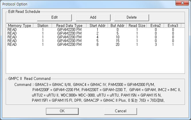 |
| <Figure 2> Example of GMPC II communication driver’s Option dialogue box |
You can set read schedule by using ![]() ,
, ![]() ,
, ![]() button and listbox of <Figure
2>.
button and listbox of <Figure
2>.
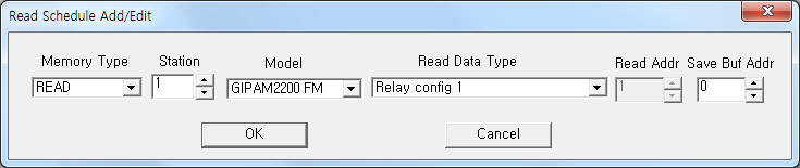 |
| <Figure 3> Example of GMPC II communication driver’s read schedule Add/Edit dialogue box |
When you click Add button or Edit button in dialogue box of <Figure 2>, dialogue box of <Figure 3> is shown.
You can write GIPAM-2200 FM equipment's setting value by using write settings.
Note) Write for GIPAM-2200 FM can control when the equipment's setting is 'remote'.
Digital Write
Digital write setting parameters are as follows:
1) PORT Port no. (0 ~ 255)
2) STATION GIPAM-2200 FM controller station number = 0 ~ 255.
3) ADDRESS Control command number(hex-decimal unit), refer to <Table 4>.
4) Extra1 Model name = PAM2200F. ( GIPAM-2200 FM model )
5) Extra2 Selection of Control or Reset command.
0 – Control command,
1 – Reset command.
Extra 2 |
Address(Sub2) |
Command contents |
Control command |
01h |
CB ON |
02h |
CB OFF |
|
25h |
Control Contact 1 ON |
|
26h |
Control Contact 2 ON |
|
27h |
Control Contact 3 ON |
|
28h |
Control Contact 4 ON |
|
2Dh |
Control Contact 1 OFF |
|
2Eh |
Control Contact 2 OFF |
|
2Fh |
Control Contact 3 OFF |
|
30h |
Control Contact 4 OFF |
|
Reset command |
00h |
CB Run Time Reset |
01h |
Active energy reset |
|
02h |
Reverse Active energy reset |
|
03h |
Reactive energy reset |
|
0Dh |
Operating time reset |
|
0Eh |
Fault reset |
|
0Fh |
All energy reset |
|
10h |
CB# ON count reset |
|
12h |
OUT#01 ON count reset |
|
13h |
OUT#02 ON count reset |
|
14h |
OUT#03 ON count reset |
|
15h |
OUT#04 ON count reset |
|
16h |
OUT#05 ON count reset |
|
17h |
OUT#06 ON count reset |
|
18h |
OUT#07 ON count reset |
|
19h |
OUT#08 ON count reset |
|
1Ch |
Io max reset |
|
1Dh |
Vo max reset |
|
1Eh |
Event record reset |
|
1Fh |
All fault record reset |
|
20h |
All record reset |
|
21h |
Calories reset |
|
22h |
NCH time reset |
|
| <Table 4> Setting element and command contents for digital write | ||
Write example 1)
PORT : 0 Station : 1, ADDRESS : 0001, EXTRA1 : PAM2200F, EXTRA2 : 0
The setting parameter shown above is CB ON control example for 1 controller station GIPAM-2200 FM.
CB ON write command can control when the controller's setting is 'remote'
Write example 2)
PORT : 0 Station : 1, ADDRESS : 0002, EXTRA1 : PAM2200F, EXTRA2 : 0
The setting parameter shown above is CB OFF control example for 1 controller station GIPAM-2200 FM.
CB OFF write command can control when the controller's setting is 'remote'
Write example 3)
PORT : 0 Station : 1, ADDRESS : 0025, EXTRA1 : PAM2200F, EXTRA2 : 0
The setting parameter shown above is Control Contact 1 ON write example for 1 controller station GIPAM-2200 FM.
Control Contact 1 ON write command can control when the controller's setting is 'remote'
Write example 4)
PORT : 0 Station : 1, ADDRESS : 002D, EXTRA1 : PAM2200F, EXTRA2 : 0
The setting parameter shown above is Control Contact 1 OFF write example for 1 controller station GIPAM-2200 FM.
Control Contact 1 OFF write command can control when the controller's setting is 'remote'
Write example 5)
PORT : 0 Station : 1, ADDRESS : 0000, EXTRA1 : PAM2200F, EXTRA2 : 1
The setting parameter shown above is CB Run Time reset example for 1 controller station GIPAM-2200 FM.
CB Run Time reset write command can control when the controller's setting is 'remote'
Write example 5)
PORT : 0 Station : 1, ADDRESS : 0022, EXTRA1 : PAM2200F, EXTRA2 : 1
The setting parameter shown above is NCH time reset example for 1 controller station GIPAM-2200 FM.
NCH time reset write command can control when the controller's setting is 'remote'
Analog Write
GMPC II communication driver for GIPAM-2200 FM model don't support analog write.
Connection of main power and communication cable are as follows.
Connection of main power
Please connect 120 V AC main power to 24, 25 connector at GIPAM-2200 FM controller's rear panel such as <Figure 4>.
<Figure 5> is appearance of GIPAM-2200 FM controller.
Note) GIPAM-2200 FM Password input method : you can input 'password' by using 'UP' and 'Down' button of frong panel. ( Inital(default) Password : 0000 )
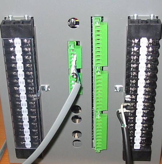 |
| <Figure 4> Connection example of main power and communication cable to GIPAM-2200 FM controller |
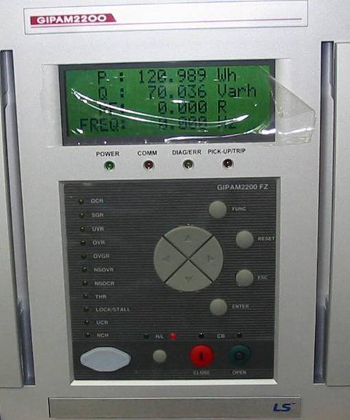 |
| <Figure 5> Appearance of GIPAM-2200 FM controller |
Connection of I-NET communication cable
Please connect I-NET RS-485 communication cable to 94 or 99 ( Rx0 ), 95 or 100 ( Rx1 ), 92 or 97 ( Tx0 ), 93 or 98 ( Tx1 ) connector such as <Figure 4>.
Note) When you connect GIPAM-2200 FM and GMPC, you have to connect Rx = Tx, Tx = Rx respectively. ( I-NET cable = offered by LSIS Co., Ltd. when you buying GMPC or GIPAM-2200 FM)
Connection of GMPC V almost equal with GMPC III. So you can refer to connection of GMPC III part.
<Figure 6> is apperance of GMPC V controller.
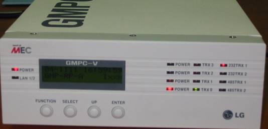 |
| <Figure 6> Apperance of GMPCV controller |
Note) Password input method : you can input 'password' by using 4 button of frong panel. ( Inital(default) Password : press 'FUNCTION', 'SELECT', 'UP', 'ENTER' button 2 times by turns )
Setting of GMPC V)
1. Time & Date : Date and Time setting of GMPC V.
2. Model : Model, protocol and communication method of GMPC V.
Model | Protocol : select GMP(I-NET protocol of GMPC) or MODBUS protocol,
Model | Media : select communication media of GMPC V.
Model | Main Port : select Primary(P) or Secondary(S).
3. Serial : select Com1 or Com2 port of GMPC V.
4. Network(This) : select LAN1, LAN2 Ethernet port.
Network(This) | Ethernet Port : select primary ethernet port of GMPC V.
Network(This) | IP_0 : input IP Address of Primary Ethernet,
Network(This) | Port_0 No_0 : input Port number of Primary Ethernet,
Network(This) | Netmask_0 : input Subnet mask of Primary Ethernet,
Network(This) | Gateway_0 : input Gateway IP Address of Primary Ethernet,
Network(This) | Host_IP0 : input Host(PC, etc) IP Address of Primary Ethernet.
After setting GMPC V controller, save the setting by using 'ENTER' button.
Also, you have to reset(power off and power on) in order to apply the setting value. (don't reset, GMPC V use the old setting value)
Note) When you using the 'Ethernet' communication, you have to set Host(PC, etc) IP address at GMPC V controller.
Also if you don't use gateway at network, please set 'Gateway' IP address to '0.0.0.0'.
Note) You must input power for the first time of GIMAC-IV, etc, and input power GMPC V.
If you input power GMPC V the first and input GIMAC-IV, etc, GMPC V can't find connected equipment. So it may not be able to communicate with connected equipment.