iCountPD Particle Counter is the driver to communicate with Particle Counter of Parker Hannifin Corp. in U.S.A.
<Figure 1> is read setting example of iCountPD Particle Counter communication driver.
|
|
| <Figure 1> Read setting example of iCountPD Particle Counter communication driver |
Device part of <Figure 1> input com port(COM4), baud rate(9600), parity bit(0), data bit(8), stop bit(1) respectively, accordint to the setting of counter.
Read schedule of iCountPD Particle Counter communication driver
Read schedule setting parameters are as follows:
1) station – don't card.
2) read command – fixed to DATA.
3) read address – don't care.
4) Save start address for Communication Server – Saving start address of Communication Server.
5) Read size – fixed to 1.
Read schedule example)
READ, 1, DATA, 0, 0, 1,
<Table 1> is data saving address and readed value for each read command of iCountPD Particle Counter communication driver.
Read Command |
Contents |
Data saving value of Communication Server | Remarks |
DATA |
read of 4, 6, 16 micro unit and NAS data |
Saving Start Address + 0 : 4 micro unit value Saving Start Address + 1 : 6 micro unit value Saving Start Address + 2 : 16 micro unit value Saving Start Address + 5 : NAS data value |
save also STRING memory |
| <Table 1> Data saving address and readed value for each read command | |||
iCountPD Particle Counter communication driver store the same data in WORD, DWORD, FLOAT, DOUBLE, INT64 memory(also save to STRING memory), but the data format are different.
If you click the icon ![]() in protocol option part at
<Figure 1>, you
can see the dialog box such as <Figure 2>. you can also set read schedule by
using this part.
in protocol option part at
<Figure 1>, you
can see the dialog box such as <Figure 2>. you can also set read schedule by
using this part.
 |
| <Figure 2> Example of iCountPD Particle Counter communication driver’s Option dialog box |
You can set read schedule by using
![]() ,
,
![]() ,
,
![]() button and listbox of <Figure
2>.
button and listbox of <Figure
2>.
 |
| <Figure 3> Example of iCountPD Particle Counter communication driver’s read schedule Add/Edit dialog box |
When you click Add button or Edit button in dialogue box of <Figure 2>, dialogue box of <Figure 3> is shown.
You can set setting value by using 'write settings'.
Digital Write
Digital write and analog write have the same setting parameters except output value.
Analog Write
Analog write setting parameters are as follows:
1) PORT Port no. (0 ~ 255)
2) STATION don't care.
3) ADDRESS saving start addres of readed value.
4) Extra1 write command : STR, STP, SRI, RMV, SSH, SML, ...
5) Extra2 don't care.
Write example 1)
PORT : 0 STATION : 0 ADDRESS : 0010 EXTRA1 : SRI 3 EXTRA2 : 0
The setting parameter shown above is Reporting Interval setting example to 3 second.
After writing, the readed setting value save at Communication Server(address = 10).
Write example 2)
PORT : 0 STATION : 0 ADDRESS : 0015 EXTRA1 : RMV EXTRA2 : 0
The setting parameter shown above is Moisture Sensor read setting example.
After writing, the readed Moisture Sensor value save 15 address Communication Server.
<Figure 4> shows the appearance of iCountPD Particle Counter.
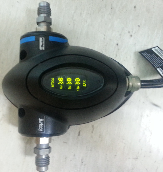 |
| <Figure 4> Appearance of iCountPD Particle Counter |