YOKOGAWA uR10000/20000 Recorder Communication Driver is the driver to communicate with 'uR10000/uR20000 Recorder' controler of Yokogawa Electric Corporation in Japan.
Note) YOKOGAWA uR10000/20000 Recorder communication driver support only 'FD' read command. (Will be upgraded)
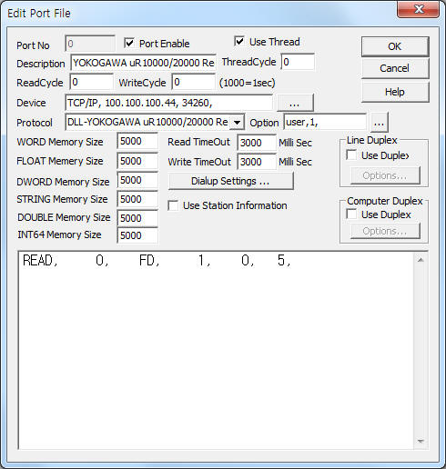
<Figure 1> is read setting example of YOKOGAWA uR10000/20000 Recorder Controller communication driver.
|
|
| <Figure 1> Read setting example of YOKOGAWA uR10000/20000 Recorder communication driver |
Device part of <Figure 1> input Connection type(TCP/IP), IP address of Recorder(100.100.100.44), TCP service port(34260) respectively.
Also 'Login ID(username)'(default = user), 'Password'(default = 1) are set by using option part.
YOKOGAWA uR10000/20000 Recorder communication driver’s read schedule
Read schedule setting parameters are as follows:
1) STATION – Don't care.
2) Read command – Command = FD.(Refer to <Table 1>)
3) Read Start Channel Nomber – Channel no. = uR10000 = 1 ~ 6, uR20000 = 1 ~ 24.
4) Save Start Address for Communication Server – Saving start address of Communication Server.
5) Reading Channel Size – uR10000 = 1 ~ 6, uR20000 = 1 ~ 24.
Read schedule example)
READ, 0, FD, 1, 0, 5,
<Table 1> is a description of 'FD' read command's stored values and contents of YOKOGAWA uR10000/20000 Recorder communication driver.
<Table 2> is bit status of 'flag' value and <Table 3> is alarm contents according to alarm value.
<Table 4> is status of 'Special Data Value'.
| Read Command | Contents | Stored Values or Output value |
| FD | Measured/ Computed Data 읽기 |
Start Add + 0 ~ 6 : year, month, day, hour, minute, second, milli
second Start Add + 7 : reserved Start Add + 8 : flag(Refer to <Table 2>) ------------------------------------------------- Start Add + 9 : Measured( 00h )/Computed( 80h ) status Start Add + 10 : read channel no. (1 ~ 6 or 1 ~ 24) Start Add + 11 ~ 14 : Alarm 1 ~ 4 status(Refer to <Table 3>) Start Add + 15 : Special Data Value (Refer to <Table 4>) Start Add + 16 : Measured/Computed Data ------------------------------------------------- Start Add + 17 ~ 24 : readed channel data value of 2nd channel ...., |
| <Table 1> 'FD' read command's stored values and contents of YOKOGAWA uR10000/20000 Recorder communication driver | ||
| Bit | Contents |
| 0 | Indicates that the internal process took too much time (computation, for example) and that FIFO dropout occurred. |
| 1 | Indicates that the FIFO acquiring interval was changed during measurement. |
| 2 | Indicates that the decimal position or unit information was changed during measurement. |
| 3 ~ | Don't care. |
| <Table 2> Bit status of 'flag' value | |
| value | Contents of alarm |
| 0 | 0 = no alarm |
| 1 ~ 8 | Alarm 발생, 1 = H(high limit alarm), 2 = L(low limit alarm), 3 = h(difference high-limit alarm), 4 = l(high limit on rate-of-change alarm), 5 = R(high limit on rate-of-change alarm), 6 = r(low limit on rate-of-change alarm), 7 = T(delay high limit alarm), 8 = t(delay low limit alarm). |
| <Table 3> Alarm contents according to alarm value | |
| value | meaning |
| 00h | normal data |
| 01h | + Over or - Over |
| 02h | – Over |
| 04h | Skip |
| 08h | Burnout (when “up” or "down" is set) |
| 10h(16) | Burnout (when “down” is set) |
| 20h(32) | Error |
| 40h(64) | Differential input |
| 80h(128) | Undefined |
| <Table 4> Status of 'Special Data Value' | |
YOKOGAWA uR10000/20000 Recorder communication driver store the same data in WORD, DWORD, FLOAT, DOUBLE memory, but the data formats are different.
If you click the icon
![]() in protocol option part, you can see the dialog
box such as <Figure 2>. you can also set read schedule by using this part.
in protocol option part, you can see the dialog
box such as <Figure 2>. you can also set read schedule by using this part.
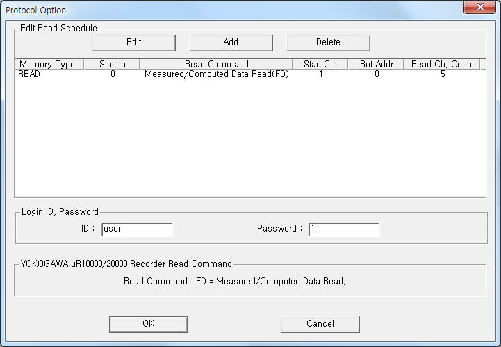 |
| <Figure 2> Example of YOKOGAWA uR10000/20000 Recorder communication driver’s Option dialog box |
You can also set read schedule by using
![]() ,
,
![]() ,
,
![]() button and listbox of <Figure 2>.
button and listbox of <Figure 2>.
Login ID and Password are set by using the part of ‘ID’, ‘Password’ shown in <Figure 2>.
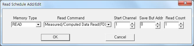 |
| <Figure 3> Example of YOKOGAWA uR10000/20000 Recorder communication driver’s read schedule Add/Edit dialog box |
When you click Add button or Edit button in dialog box of <Figure 2>, dialog box of <Figure 3> will be shown.
YOKOGAWA uR10000/20000 Recorder communication driver don’t support ‘Write setting’.(Will be upgraded)
<Figure 4> shows the appearance of YOKOGAWA uR10000 Recorder.
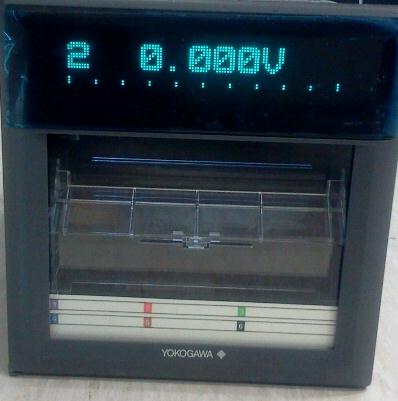 |
| <Figure 4> Appearance of YOKOGAWA uR10000 Recorder |