Utisol Lighting Controller communication driver is the driver to communicate with Utisol lighting controller.
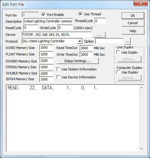
<Figure 1> is read setting example of Utisol Lighting Controller communication driver.
|
|
| <Figure 1> Read setting example of Utisol Lighting Controller communication driver |
Device part of <Figure 1> input Device type(TCP/IP), IP address of PLC(192.168.185.24), service port of TCP/IP protocol ( 5024 ),respectively, according to setting of controller.
Utisol Lighting Controller communication driver read schedule
Read schedule setting parameters are as follows:
1) Private Address – 0 ~ 255 Private Address. ( don't cate )
2) Read command – command = fixed to CURR.
3) Read start address – don't care.
4) Save start address for Communication Server – Saving start address of Communication Server.
5) Read Size – fixed to 1. ( refer to <table 1> )
Read schedule example)
READ, 22, CURR, 1, 0, 1,
<Table 1> is data saving address and contents for CURR read command.
| Data saving address | Contents | Remarks |
| start add + 0 | private address of controller | don't care |
| start add + 1 | RxTx value | 1 ~ 7 |
| start add + 2 | sensor type | |
| start add + 3 | micom type | |
| start add + 4 | group address of controller | |
| start add + 5 | high | |
| start add + 6 | low | |
| start add + 7 | watt Level | real value = readed value x 10 |
| start add + 8 | type | |
| start add + 9 | sensor high rate | |
| start add + 10 | status | 1 ~ 6 |
| start add + 11 | KWh | |
| start add + 12 | main command | 101 = response command |
| start add + 13 | sub command | |
| start add + 14 | time | |
| start add + 15 | source private address | |
| start add + 16 | destination private address | |
| start add + 17 | source group address | |
| start add + 18 | destination group address | |
| start add + 19 ~ 21 | destination 1 ~ 3 group address | |
| start add + 22 | reserved | |
| <Table 1> Data saving address and contents for CURR read command | ||
Utisol Lighting Controller communication driver store the same data in WORD, DWORD, FLOAT, DOUBLE memory, but the data formats are different.
If you click the icon
![]() in protocol option part, you can see the dialogue
box such as <Figure 2>. you can also set read schedule by using this part.
in protocol option part, you can see the dialogue
box such as <Figure 2>. you can also set read schedule by using this part.
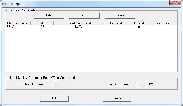 |
| <Figure 2> Example of Utisol Lighting Controller communication driver’s Option dialogue box |
You can also set read schedule by using
![]() ,
,
![]() ,
,
![]() button and listbox of <Figure 2>.
button and listbox of <Figure 2>.
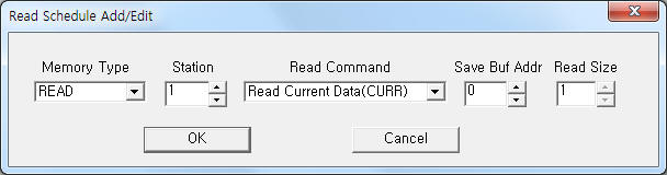 |
| <Figure 3> Example of Utisol Lighting Controller communication driver’s read schedule Add/Edit dialogue box |
When you click Add button or Edit button in dialogue box of <Figure 2>, dialogue box of <Figure 3> will be shown.
You can set power value of Utisol Lighting controller by using write settings.
Digital write
Digital write and analog write have the same setting parameters except output value(0 or 1).
Analog write
Analog write setting parameters are as follows:
1) PORT port no. (0 ~ 255)
2) STATION don't care.
3) ADDRESS don't care.
4) EXTRA 1 write command =CURR, POWER.
CURR : corrent data reading command,
POWER : power value( KWh ) setting command.
5) EXTRA 2 readed value saving start address when CURR command.
Write example 1)
PORT:0, station:0, ADDRESS:0000, Extra1:CURR, Extra2 : 100
The setting parameter shown above is an example of current data reading.
After reading, the readed data save 100 ~ 122 WORD, DWORD, FLOAT, DOUBLE memory.
Write example 2)
PORT:0, station:0, ADDRESS:0000, Extra1:POWER, Extra2 : 0
The setting parameter shown above is power value( KWh ) setting example.
Note) Errors often occur when setting power value( KWh ).
In this case, please set two or more times write command.
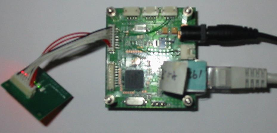
<Figure 4> is appearance of Utisol Lighting Controller.
 |
|
<Figure 4> Appearance of Utisol Lighting Controller |