SmartOn Dimming Module communication driver is the driver to communicate with wireless dimming controller of SmartOn Techonology in Korea.
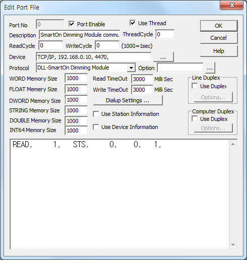
<Figure 1> is read setting example of SmartOn Dimming Module communication driver.
|
|
| <Figure 1> Read setting example of SmartOn Dimming Module communication driver |
Device part of <Figure 1> input Device type(TCP/IP), IP address of PLC(192.168.0.10), service port of TCP/IP protocol ( 4470 ),respectively, according to setting of controller.
SmartOn Dimming Module communication driver read schedule
Read schedule setting parameters are as follows:
1) Dimming switch address and channel number – lower byte = 1 ~ 64 dimming switch address.
higher = 1 ~ 3 dimming switch channel address. ( 0 = 1 channel )
2) Read command – command = STS, PIRID, PIR_A, LOCK, ILLU_A, ILLU, G_SW, PIR, CH. ( refer to <Table 1> )
3) Read index, group, channel address – index/group number or channel number.
STS command : 0 ~ 3 index number,
G_SW command : 1 ~ 10 group ID,
PIR, PIRID, ILLU command : PIR channel number,
other command : don't care.
4) Save start address for Communication Server – Saving start address of Communication Server.
5) Lighting ID – lighting ID when PIR, PIRID, ILLU command.
Read schedule example)
READ, 1, STS, 0, 0, 1,
<표 1> is read command and contents of SmartOn Dimming Module communication driver.
<Table 2> ~ <Table 4> is data saving address and contents for STS read command of index 0/1, 2, 3.
<Table 5> ~ <Table 8> is data saving address and contents for PIRID, ILLU, G_SW, PIR read command.
| Read command | Contents | Remarks |
| STS | read of dimming switch status | index 0 = 0 ~ 15 lighting switch control LED index 1 = 16 ~ 32 lighting switch control LED index 2 = 2 of illumination status, 2 of PIR status index 3 = 1 ~ 9 group status value |
| PIRID | read of lighting ID status of controlled by PIR sensors | channel number, status read of each lighting ID |
| PIR_A | read of PIR auto/manual status | Start addr + 0 : auto, manual status ( 0 = auto, 1 = manual ) |
| LOCK | read of switch lock/unlock status | Start addr + 0 ~ 2 : switch 1 ~ 3 lock/unlock status ( 0 = unlock, 1 = lock ) |
| ILLU_A | read of switch illumination auto/manual status | Start addr + 0 : auto, manual status ( 0 = auto, 1 = manual ) |
| ILLU | read of illumination sensor status | channel number, status read of each lighting ID |
| G_SW | read of switch group status | 1 ~ 10 group status value |
| PIR | read of PIR sensor status | channel number, status read of each lighting ID |
| CH | read of dimming switch zig channel | Start addr + 0 : zig channel value |
| <Table 1> Read command and contents of SmartOn Dimming Module communication driver | ||
| Data saving address | Contents | Remakrs |
| Start addr + 0 | frequency channel number of 1st lighting | |
| Start addr + 1 | module number of wireless module | 0 ~ 1024 |
| Start addr + 2 | retention time | 0 ~ 255 second |
| Start addr + 3 | dimming time | |
| Start addr + 4 | maximum brightness | 0 ~ 100%, max. brightness >= min. brightness |
| Start addr + 5 | minimum brightness | 0 ~ 100%, max. brightness >= min. brightness |
| Start addr + 6 | auto /manual status | 0 = automatic, 1 = manual, dimming control when manual |
| Start addr + 7 | current brightness | 0 ~ 100% |
| Start addr + 8 | strength of received signal | -127 ~ 128 |
| Start addr + 9 ~ 17 | frequency channel number of 2nd lighting ~ ..., strength of received signal |
|
| Start addr + 18 ~ 26 | frequency channel number of 3rd lighting ~ ..., strength of received signal |
|
| ... | ||
| Start addr + 135 ~ 143 | frequency channel number of 10th lighting ~ ..., strength of received signal |
|
| <Table 2> Data saving address and contents for STS read command of index 0, 1 | ||
| Data saving address | Contents | Remakrs |
| Start addr + 0 | retention time of 1st illumination | 0 ~ 255 second |
| Start addr + 1 | dimming time | 1 ~ 255 second |
| Start addr + 2 | maximum brightness | 0 ~ 100%, max. brightness >= min. brightness |
| Start addr + 3 | minimum brightness | 0 ~ 100%, max. brightness >= min. brightness |
| Start addr + 4 | auto /manual status | 0 = automatic, 1 = manual, dimming control when manual |
| Start addr + 5 | current brightness | 0 ~ 100% |
| Start addr + 6 | strength of received signal | -127 ~ 128 |
| Start addr +7 ~ 9 | reserved 1 ~ 3 | |
| Start addr + 10 ~ 19 | retention time of 2nd illumination ~ ..., reserved 1 ~ 3 |
|
| Start addr + 20 ~ 29 | retention time of 1st PIR ~ ..., reserved 1 ~ 3 |
|
| Start addr + 30 ~ 39 | retention time of 2nd PIR ~ ..., reserved 1 ~ 3 |
|
| <Table 3> Data saving address and contents for STS read command of index 2 | ||
| Data saving address | Contents |
| Start addr + 0 ~ 9 | status value of 1 ~ 9 group |
| <Table 4> Data saving address and contents for STS read command of index 3 | |
| Data saving address | Contents | Remakrs |
| Start addr + 0 | control period between lighting | 0 ~ 255, 30msec unit, 10 = 300msec, 100=3second |
| Start addr + 1 | number of lighting | 0 ~ 32 ( default : 32 ) |
| Start addr + 2 ~ 33 | lighting ID 1 ~ 32 | 0 ~ 1024 |
| Start addr + 34 ~ 35 | reserved1, 2 | |
| <Table 5> Data saving address and contents for PIRID read command | ||
| Data saving address | Contents | Remakrs |
| Start addr + 0 | illumination sensor Level 1 | fixed value |
| Start addr + 1 | illumination sensor Level 2 | 0 ~ 100% |
| Start addr + 2 | strength of received signal | -127 ~ 128 |
| <Table 6> Data saving address and contents for ILLU read command | ||
| Data saving address | Contents | Remakrs |
| Start addr + 0 ~ 31 | module ID 1 ~ 32 number | 0 ~ 1024 |
| <Table 7> Data saving address and contents for G_SW read command | ||
| Data saving address | Contents | Remakrs |
| Start addr + 0 | auto /manual status | 0 = automatic, 1 = manual, dimming control when manual |
| Start addr + 1 | PIR(Doppler) sensor Level | 0 ~ 255, 단위 50mV, 100 : 5.0V, Doppler = 0 ~ 100% |
| Start addr + 2 | operation status | 0 = ON, 1 = OFF |
| Start addr + 3 | strength of received signal | -127 ~ 128 |
| <Talbe 8> Data saving address and contents for PIR read command | ||
SmartOn Dimming Module communication driver store the same data in WORD, DWORD, FLOAT, DOUBLE memory, but the data format are different.
If you click the icon ![]() in protocol option part at
<Figure 1>, you
can see the dialog box such as <Figure 2>. you can also set read schedule by
using this part.
in protocol option part at
<Figure 1>, you
can see the dialog box such as <Figure 2>. you can also set read schedule by
using this part.
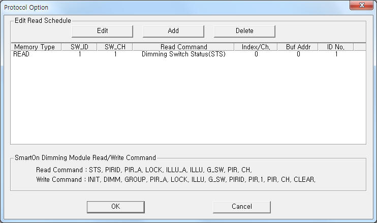 |
| <Figure 2> Example of SmartOn Dimming Module communication driver’s Option dialog box |
You can set read schedule by using ![]() ,
, ![]() ,
, ![]() button and listbox of <Figure
2>.
button and listbox of <Figure
2>.
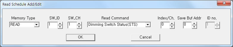 |
| <Figure 3> Example of SmartOn Dimming Module communication driver’s read schedule Add/Edit dialog box |
When you click Add button or Edit button in dialogue box of <Figure 2>, dialogue box of <Figure 3> is shown.
You can set SmartOn Dimming Module by using 'write settings'.
Digital Write
Digital write and analog write have the same setting parameters except output value.
Analog Write
Analog write setting parameters are as follows:
1) PORT Port no. (0 ~ 255)
2) STATION Dimming switch address and channel number.
lower byte = 1 ~ 64 dimming switch address.
higher = 1 ~ 3 dimming switch channel address. ( 0 = 1 channel )
3) ADDRESS channel number or group number.( decimal unit )
INIT, DIMM, PIR, PIR.1, PIRID write command : channel number,
GROUP, G_SW write command : 1 ~ 10 group number,
other command : don't care.
4) Extra1 writte command = INIT, DIMM, GROUP, PIR_A, LOCK, ILLU, G_SW, PIRID, PIR.1, PIR, CH, CLEAR. ( refer to <Table 9> )
5) Extra2 wireless module address( 0 ~ 1024 ) when DIMM, PIR, PIR.1, PIRID write command.
<Table 9> is write command and setting parameter of SmartOn Dimming Module communication driver.
| Write command | Contents | ADDRESS | EXTRA 2 | Output value |
| INIT | setting of dimming LED inital value | channel number | don't care | 0 ~ 999 file number for setting value reading, refer to <Table 10> |
| DIMM | control of indivisual dimming | 0 ~ 1024 wireless module address | 0 ~ 100% | |
| GROUP | groug dimming control | 1 ~ 10 group number | don't care | 0 ~ 100% |
| PIR_A | PIR automatic/manual control | don't care | 0 = automatic, 1 = manual | |
| LOCK | write of switch lock/unlock status | 0 = unlock, 1 = lock | ||
| ILLU | illumination sensor automatic/manual control | 0 = automatic, 1 = manual | ||
| G_SW | switch group setting | 1 ~ 10 group number | 0 ~ 999 file number for setting value reading, refer to <Table 10> |
|
| PIRID | lighting ID setting of controlled by PIR sensor | channel number | 0 ~ 1024 wireless module address | |
| PIR | PIR sensor inital value setting to 'manual' | PIR = 0 ~ 255, unit 50mV, 100 : 5.0V, Doppler = 0 ~ 100% |
||
| PIR.1 | PIR sensor inital value setting to 'automatic' | |||
| CH | dimming switch zig channel value seting | don't care | don't care | zig channel value |
| CLEAR | memory_all group clear command | don't care | ||
| <Table 9> Write command and setting parameter of SmartOn Dimming Module communication driver | ||||
| Command | Filename | Input method | Remarks |
| INIT | work folder\SCAN\INIT_LED_%03d.ini | refer to <Table 11> | %03d = 0 ~ 999 output value |
| G_SW | work folder\SCAN\GROUP_SWITCH_%03d.ini | ||
| PIRID | work folder\SCAN\PIR_ID_%03d.ini | ||
| <Table 10> Filename and contents for INIT, G_SW, PIRID write command | |||
| 구분 | Input method |
| input method | input all setting value at 1st line. each argument is a comma-delimited. |
| number of input element | INIT = 9 G_SW = 32 PIRID = 34 |
| contents of INIT command |
setting wireless module address(0 ~ 1024), retention time(0 ~ 255), dimming time(1 ~ 255), maximum brightness (0 ~ 100), minimum brightness (0 ~ 100), auto /manual (0 = automatic, 1 = manual), current brightness(0 ~ 100), Reserved 1, Reserved 2 |
| contents of G_SW command |
input 32 zig lighting address ID value(0 ~ 1024) |
| contents of PIRID command |
0 or 1 index number, 0 ~ 255 lighting control time, input 32 module ID value(0 ~ 1024) |
| <Table 11> Setting value input method of INIT, G_SW, PIRID write command | |
Write example 1)
PORT:0, station:1, ADDRESS:0001, Extra1:DIMM, Extra2 : 1
The setting parameter shown above is indivisual dimming setting( 0 ~ 100 % ) example for 1 switch, 1 switch channel, 1 channel, 1 indivisual ID.
Write example 2)
PORT:0, station:1, ADDRESS:0001, Extra1:GROUP, Extra2 : 0
The setting parameter shown above is group dimming setting( 0 ~ 100 % ) example for 1 switch, 1 switch channel, 1 group.
Write example 3)
PORT:0, station:1, ADDRESS:0015, Extra1:INIT, Extra2 : 0, Output value = 1,
The setting parameter shown above is dimming LED inital value setting example for 1 switch, 1 switch channel, 15( 0Fh ) channel.
The setting value read 1st line( 9 setting data ) of 'work folder\SCAN\INIT_LED_001.ini' file. ( refer to <Table 10> ~ <Table 11> )
Write example 4)
PORT:0, station:1, ADDRESS:0001, Extra1:G_SW, Extra2 : 0, Output value = 2,
The setting parameter shown above is switch group setting setting example for 1 switch, 1 switch channel, 1 group.
The setting value read 1st line( 32 setting data ) of 'work folder\SCAN\GROUP_SWITCH_002.ini' file. ( refer to <Table 10> ~ <Table 11> )
Write example 5)
PORT:0, station:1, ADDRESS:0015, Extra1:PIRID, Extra2 : 1, Output value = 999,
The setting parameter shown above is lighting ID setting of controlled by PIR sensor example for 1 switch, 1 switch channel, 15( 0Fh ) cannel, 1 module address.
The setting value read 1st line( 32 setting data ) of 'work folder\SCAN\PIR_ID_999.ini' file. ( refer to <Table 10> ~ <Table 11> )
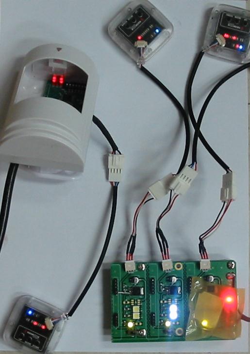
<Figure 4> is appearance of SmartOn Dimming Module.
<Figure 5> is appearance of wireless module.
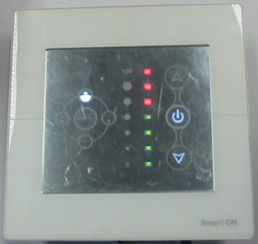 |
| <Figure 4> Appearance of SmartOn Dimming Module |
 |
| <Figure 5> Appearance of wireless module |