SLR5100 RF Protocol is the driver to communicate with RF module of SiLion Co. Ltd,. in China.
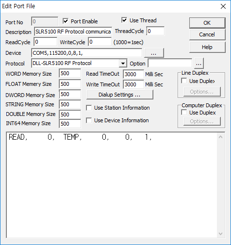
<Figure 1> is read setting example of SLR5100 RF Protocol communication driver.
|
|
| <Figure 1> Read setting example of SLR5100 RF Protocol communication driver |
Device part of <Figure 1> input com port(COM5), baud rate(115200), parity bit(0), data bit(8), stop bit(1) respectively, accordint to the setting of controller(module).
Read schedule of SLR5100 RF Protocol communication driver
Read schedule setting parameters are as follows:
1) station – don't care.
2) read command – Command : TEMP, VER, ANT, OUT, MODE, INV_T( refer to <Table 1> ).
3) read start address – sub-command (read option) when ANT, INV_T read command.
4) Save start address for Communication Server – Saving start address of Communication Server.
5) Read size – fixed to 1.
Read schedule example)
READ, 0, TEMP, 0, 0, 1,
<Table 1> is data saving address and readed value for each read command.
Read Command |
Contetns |
Data saving value of Communication Server | Remarks |
TEMP |
read of current temperature of module |
Saving Start Address + 0 : status code of read/write Saving Start Address + 1 : temperature of module |
0 : Ok, 1 ~ FFFFh : error (don't exist temperature value when error) |
VER |
read of BOOTLOADER/FIRMWARE version information |
Saving Start Address + 0 : status code of read/write Saving Start Address + 1 : bootloader version info 4byte Saving Start Address + 2 : hardware version info 4byte Saving Start Address + 3 : firmware date info 4byte |
0 : Ok, 1 ~ 0xFFFF : error(don't exist info. value when error) default :13041500h default :A3000001h last compiled date 4byte(2013.05.22) |
ANT |
read of operation antenna check sub-command = 2 (default) |
Saving Start Address + 0 : status code of read/write Saving Start Address + 1 : Tx ant number Saving Start Address + 2 : Rx ant number |
0 : Ok, 1 ~ 0xFFFF : error (don't exist ant value when error) |
read of all antenna read/write transmission output sub-command = 3 |
Saving Start Address + 0 : status code of read/write Saving Start Address + 1 ~ 3 : antenna output value of no. 1 Saving Start Address + 4 ~ 6 : antenna output value of of no. 2 Saving Start Address + 7 ~ 9 : antenna output value of of no. 3 Saving Start Address + 10 ~ 12 : antenna output value of of no. 4 Saving Start Address + 13 ~ 15 : antenna output value of of no. 5 Saving Start Address + 16 ~ 18 : antenna output value of of no. 6 Saving Start Address + 19 ~ 21 : antenna output value of of no. 7 Saving Start Address + 22 ~ 24 : antenna output value of of no. 8 |
0 : Ok, 1 ~ 0xFFFF : error (don't exist ant value when error) saving order = antenna number, read output, write output value |
|
read of all antenna read/write transmission output, setting time sub-command = 4 |
Saving Start Address + 0 : status code of read/write Saving Start Address + 1 ~ 4 : antenna output, setting time of no. 1 Saving Start Address + 5 ~ 8 : antenna output, setting time of no. 2 Saving Start Address + 9 ~ 12 : antenna output, setting time of no. 3 Saving Start Address + 13 ~ 16 : antenna output, setting time of no. 4 Saving Start Address + 17 ~ 20 : antenna output, setting time of no. 5 Saving Start Address + 21 ~ 24 : antenna output, setting time of no. 6 Saving Start Address + 25 ~ 28 : antenna output, setting time of no. 7 Saving Start Address + 29 ~ 32 : antenna output, setting time of no. 8 |
0 : Ok, 1 ~ 0xFFFF : error (don't exist ant value when error) saving order = antenna number, read output, write output, setting time |
|
read of all antenna connection status sub-command = 5 |
Saving Start Address + 0 : status code of read/write Saving Start Address + 1 : Tx ant number Saving Start Address + 2 : Rx ant number |
0 : Ok, 1 ~ 0xFFFF : error (don't exist ant value when error) |
|
OUT |
read of transmission output info. |
Saving Start Address + 0 : status code of read/write Saving Start Address + 1 : current Tx power Saving Start Address + 2 : max Tx power Saving Start Address + 3 : min Tx power |
0 : Ok, 1 ~ 0xFFFF : error(don't exist info value when error) return default value max transmission output(default : 30 dbm) min transmission output(default : 19 dbm) |
MODE |
read of bootloader/app layer info. |
Saving Start Address + 0 : status code of read/write Saving Start Address + 1 : bootloader/app layer value |
0 : Ok, 1 ~ 0xFFFF : error(don't exist layer value when error) 11h = bootloader layer, 12h : app layer |
INV_T |
read of information for all the inventoried tags sub-command : 0 = unconfirmed tag(default) 1= confirmed tag by 29h command |
Saving Start Address + 0 : status code of read/write Saving Start Address + 1 : number of tag Saving Start Address + 2 ~ 4 : read count, RSSI, antenna ID Saving Start Address + 5 : frequency fo inventoried tag Saving Start Address + 6 : system time of module Saving Start Address + 7 : RFU value Saving Start Address + 8 : Tag data Saving Start Address + 9 : PC word value Saving Start Address + 10 : Tag EPC ID value Saving Start Address + 11 ~ 19 : read count, .... of 2nd tag ... |
0 : Ok, 1 ~ 0xFFFF : error (don't exist tag info. value when error) unit : KHZ unit : ms save also tag string to STRING memory save also tag string to STRING memory |
| <Table 1> Data saving address and readed value for each read command | |||
SLR5100 RF Protocol communication driver store the same data in WORD, DWORD, FLOAT, DOUBLE, INT64 memory, but the data format are different.
Ttag data and tag EPC ID value also save STRING memory.
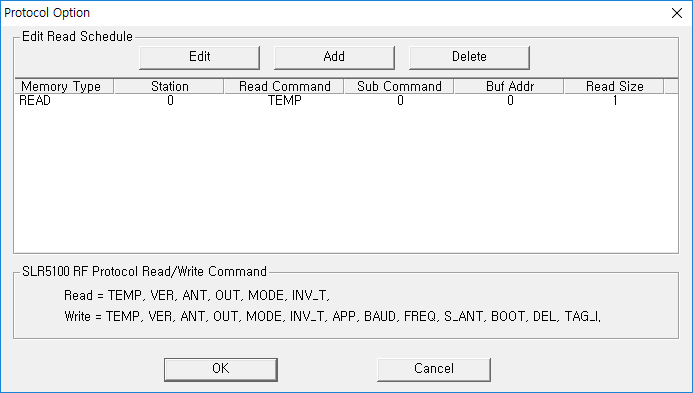
If you click the icon ![]() in protocol option part at
<Figure 1>, you
can see the dialog box such as <Figure 2>. you can also set read schedule by
using this part.
in protocol option part at
<Figure 1>, you
can see the dialog box such as <Figure 2>. you can also set read schedule by
using this part.
 |
| <Figure 2> Example of SLR5100 RF Protocol communication driver’s Option dialog box |
You can set read schedule by using
![]() ,
,
![]() ,
,
![]() button and listbox of <Figure
2>.
button and listbox of <Figure
2>.
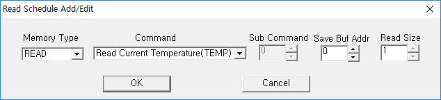 |
| <Figure 3> Example of SLR5100 RF Protocol communication driver’s read schedule Add/Edit dialog box |
When you click Add button or Edit button in dialogue box of <Figure 2>, dialogue box of <Figure 3> is shown.
You can set setting value by using 'write settings'.
Digital Write
Digital write and analog write have the same setting parameters except output value.
Analog Write
Analog write setting parameters are as follows:
1) PORT Port no. (0 ~ 255)
2) STATION setting value for write command. ( refer to <Table 2>)
3) ADDRESS saving start addres of read value( status code, ..., 10digit number ).
4) Extra1 write command : TEMP, VER, ANT, OUT, MODE, INV_T, APP, BAUD, FREQ, S_ANT, BOOT, DEL, TAG_I. ( refer to <Table 2> )
5) Extra2 sub-setting command according to Write command. ( refer to <Table 2> )
6) Output value setting value according to write command. ( refer to <Table 2> )
<Table 2> is output value and setting parameter for write command.
Write Command(Extra1) |
Contents and Station |
Data saving value of Communication Server(according to Address) |
Extra2 |
Output Value |
TEMP |
read of temperature current module, station : don't care |
Saving Start Address + 0 : status code of read/write(refer to <Table 1>) Saving Start Address + 1 : temperature value of module |
don't care | don't care |
VER |
read of BOOTLOADER/FIRMWARE version info., station : don't care |
Saving Start Address + 0 : status code of read/write(refer to <Table 1>) Saving Start Address + 1 : bootloader version info. 4byte Saving Start Address + 2 : hardware version info. 4byte Saving Start Address + 3 : firmware date info. 4byte |
||
ANT |
read of operation antenna check, station : don't care |
Saving Start Address + 0 : status code of read/write(refer to <Table 1>) Saving Start Address + 1 : Tx ant number Saving Start Address + 2 : Rx ant number |
2(default) |
|
read of all antenna read/write transmission output
station : don't care |
Saving Start Address + 0 : status code of read/write(refer to <Table 1>) Saving Start Address + 1 ~ 3 : antenna output value of no. 1 Saving Start Address + 4 ~ 6 : antenna output value of no. 2 Saving Start Address + 7 ~ 9 : antenna output value of no. 3 Saving Start Address + 10 ~ 12 : antenna output value of no. 4 Saving Start Address + 13 ~ 15 : antenna output value of no. 5 Saving Start Address + 16 ~ 18 : antenna output value of no. 6 Saving Start Address + 19 ~ 21 : antenna output value of no. 7 Saving Start Address + 22 ~ 24 : antenna output value of no. 8 |
3 |
||
read of all antenna read/write transmission output, setting time
station : don't care |
Saving Start Address + 0 : status code of read/write(refer to <Table 1>) Saving Start Address + 1 ~ 4 : 1antenna output, setting time of no. 1 Saving Start Address + 5 ~ 8 : 2antenna output, setting time of no. 1 Saving Start Address + 9 ~ 12 : 3antenna output, setting time of no. 1 Saving Start Address + 13 ~ 16 : 4antenna output, setting time of no. 1 Saving Start Address + 17 ~ 20 : 5antenna output, setting time of no. 1 Saving Start Address + 21 ~ 24 : 6antenna output, setting time of no. 1 Saving Start Address + 25 ~ 28 : 7antenna output, setting time of no. 1 Saving Start Address + 29 ~ 32 : 8antenna output, setting time of no. 1 |
4 |
||
read of all antenna connection status station : don't care |
Saving Start Address + 0 : status code of read/write(refer to <Table 1>) Saving Start Address + 1 : Tx ant number Saving Start Address + 2 : Rx ant number |
5 |
||
OUT |
read of transmission output info., station : don't care |
Saving Start Address + 0 : status code of read/write Saving Start Address + 1 : current Tx power Saving Start Address + 2 : max Tx power Saving Start Address + 3 : min Tx power |
don't care |
|
MODE |
read of bootloader/app layer info., station : don't care |
Saving Start Address + 0 : status code of read/write(refer to <Table 1>) Saving Start Address + 1 : bootloader/app layer value |
||
INV_T |
read of information for all the inventoried tags
station : don't care |
Saving Start Address + 0 : status code of read/write Saving Start Address + 1 : number of tag Saving Start Address + 2 ~ 4 : read count, RSSI, antenna ID Saving Start Address + 5 : frequency fo inventoried tag Saving Start Address + 6 : system time of module Saving Start Address + 7 : RFU value Saving Start Address + 8 : Tag data Saving Start Address + 9 : PC word value Saving Start Address + 10 : Tag EPC ID value Saving Start Address + 11 ~ 19 : read count, .... of 2nd tag ... |
0 = unconfirmed tag(default) 1 = confirmed tag by 29h command |
|
APP |
move to app. layer, station : don't care |
Saving Start Address + 0 : status code of read/write(refer to <Table 1>) Saving Start Address + 1 : bootloader version info. 4byte Saving Start Address + 2 : hardware version info. 4byte Saving Start Address + 3 : firmware date info. 4byte |
don't care | |
BAUD |
baud rate setting command, station : don't care |
Saving Start Address + 0 : status code of read/write (refer to <Table 1>) |
output value = 9600, 19200, 38400, 57600, 115200, 230400, 460800, 921600 |
|
FREQ |
operation frequency setting command, station : don't care |
1(north america,902-928), 6(china,920-925), 8(europe,865-867), 10(china 2, 840-845) |
||
S_ANT |
antenna terminal setting command, station = don't care |
0 : use of 1 logical antenna | Tx/Rx Ant Num (1byte value) |
|
antenna terminal setting command, station = 1 ~ 4 no. of antenna |
2 : use of 1 ~ 4 logical antenna | Tx/Rx Ant Num (station : 1 ~ 4 = 1 ~ 4 byte value) |
||
antenna terminal setting command, station = Tx/Rx Ant Num, logical value of transmission antenna |
3 : setting of antenna transmission output |
higher 2 byte : read transmission output, lower 2 byte : write transmission output |
||
antenna terminal setting command, station = Tx/Rx Ant Num, logical value of transmission antenna |
4 : setting of antenna transmission output and setting time |
higher 2 byte : read transmission output, lower 2 byte : write transmission output, antenna setting time : fixed to 01F4h |
||
BOOT |
setting command to bootloader layer station : don't care |
don't care | don't care | |
DEL |
delete command for tag cache, station : don't care |
don't care | ||
TAG_I |
multi-tag inventory command ( case of don't use filting ), station : don't care |
Saving Start Address + 0 : status code of read/write(refer to <Table 1>) Saving Start Address + 1 : select option( 0 ) Saving Start Address + 2 : select flags ( 2byte data ) Saving Start Address + 3 : tag found |
inventory time ( 2 byte, unit : ms) |
|
| <Table 2> Output value and setting parameter for write command | ||||
Write example 1)
PORT : 0 STATION : 0 ADDRESS : 0010 EXTRA1 : APP EXTRA2 : 0
The setting parameter shown above is layer changing to 'app' mode example. ( after write, writing result value save at 10 addres memory, normal operation = 0000h )