PEMS TCU Protocol is the driver to communicate with Power monitoring controller of M.Nextec Inc. in Korea.
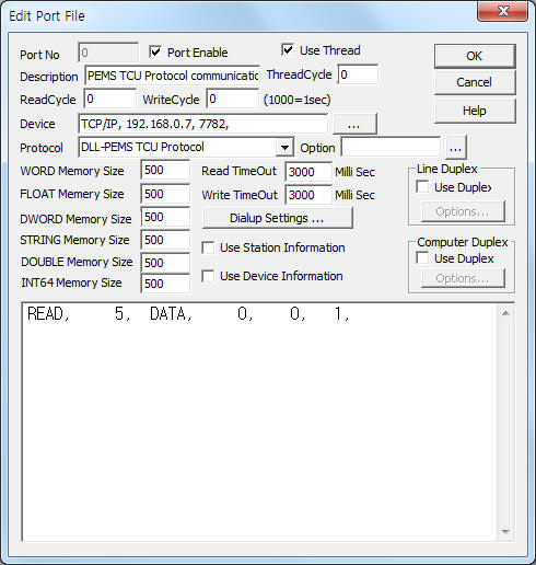
<Figure 1> is read setting example of PEMS TCU Protocol communication driver.
|
|
| <Figure 1> Read setting example of PEMS TCU Protocol communication driver |
Device part of <Figure 1> input Protocol type(TCP/IP), IP Address of controller(192.168.0.7), service port(7782) respectively, accordint to the setting of controller.
Read schedule of PEMS TCU Protocol communication driver
Read schedule setting parameters are as follows:
1) TCU ID – 0 ~ 255 TCU ID.
2) Read command – fixed to DATA. ( refer to <Table 1> )
3) Read start address – don't care.
4) Save start address for Communication Server – Saving start address of Communication Server.
5) Read size – fixed to 1.
Read schedule example)
READ, 5, DATA, 0, 0, 1,
<Table 1> is readed data saving value and contents of DATA command for PEMS TCU Protocol communication driver.
Contents |
Data saving value for Communication Server |
Remarks |
PCM 데이터 읽기 |
Saving Start Address + 0 : command of PCM station 1 Saving Start Address + 1 : status of PCM station 1 Saving Start Address + 2 : total waiting power value of PCM station 1 Saving Start Address + 3 : master current value of PCM station 1 Saving Start Address + 4 : setting value of PCM station 1 Saving Start Address + 5~6 : reserved data of PCM station 1 ... ... Saving Start Address + 217 : command of PCM station 32 Saving Start Address + 218 : status of PCM station 32 Saving Start Address + 219 : total waiting power value of PCM station 32 Saving Start Address + 220 : master current value of PCM station 32 Saving Start Address + 221 : 32번 setting value of PCM station 32 Saving Start Address + 222~223 : reserved data of PCM station 32 |
Low byte : cmd 0, high byte : cmd 1 Low byte : status 0, high byte : status 1 W unit W unit W unit |
| <Table 1> Readed data saving value and contents of DATA command for PEMS TCU Protocol communication driver | ||
PEMS TCU Protocol communication driver store the same data in WORD, DWORD, FLOAT, DOUBLE memory, but the data format are different.
If you click the icon ![]() in protocol option part at
<Figure 1>, you
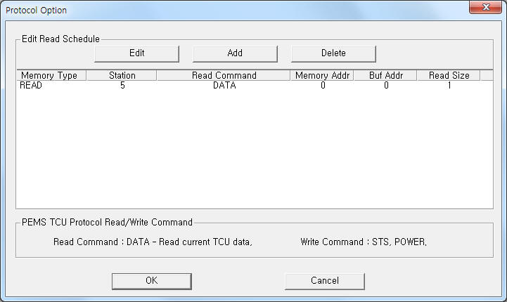
can see the dialog box such as <Figure 2>. you can also set read schedule by
using this part.
in protocol option part at
<Figure 1>, you
can see the dialog box such as <Figure 2>. you can also set read schedule by
using this part.
 |
|
<Figure 2> Example of PEMS TCU Protocol communication driver’s Option dialog box |
You can set read schedule by using
![]() ,
,
![]() ,
,
![]() button and listbox of <Figure
2>.
button and listbox of <Figure
2>.
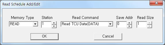 |
| <Figure 3> Example of PEMS TCU Protocol communication driver’s read schedule Add/Edit dialog box |
When you click Add button or Edit button in dialogue box of <Figure 2>, dialogue box of <Figure 3> is shown.
You can control PEMS TCU by using 'write settings'.
Digital Write
Digital write and analog write have the same setting parameters except output value.
Analog Write
Analog write setting parameters are as follows:
1) PORT Port no. (0 ~ 255)
2) STATION 0 ~ 255 TCU ID.
3) ADDRESS 0 ~ 255 PCM ID ( 0 = total PCM )
4) Extra1 write command : STS, POWER.
STS : status setting command,
POWER : waiting power value setting command.
5) Extra2 don't care.
Write example 1)
PORT : 0 STATION : 5 ADDRESS : 0001 EXTRA1 : STS EXTRA2 : 0 , Output Value = 3010h
The setting parameter shown above is status setting example for TCU 5, PCM 1. The setting status is 'Manual + forcing On'
( 2020h output value : Automatic setting, 2000h output value : manaul setting )
Write example 2)
PORT : 1 STATION : 5 ADDRESS : 0002 EXTRA1 : POWER EXTRA2 : 0
The setting parameter shown above is waiting power setting example for TCU 5, PCM 2.
<Figure 4> shows the appearance of PEMS TCU controller.
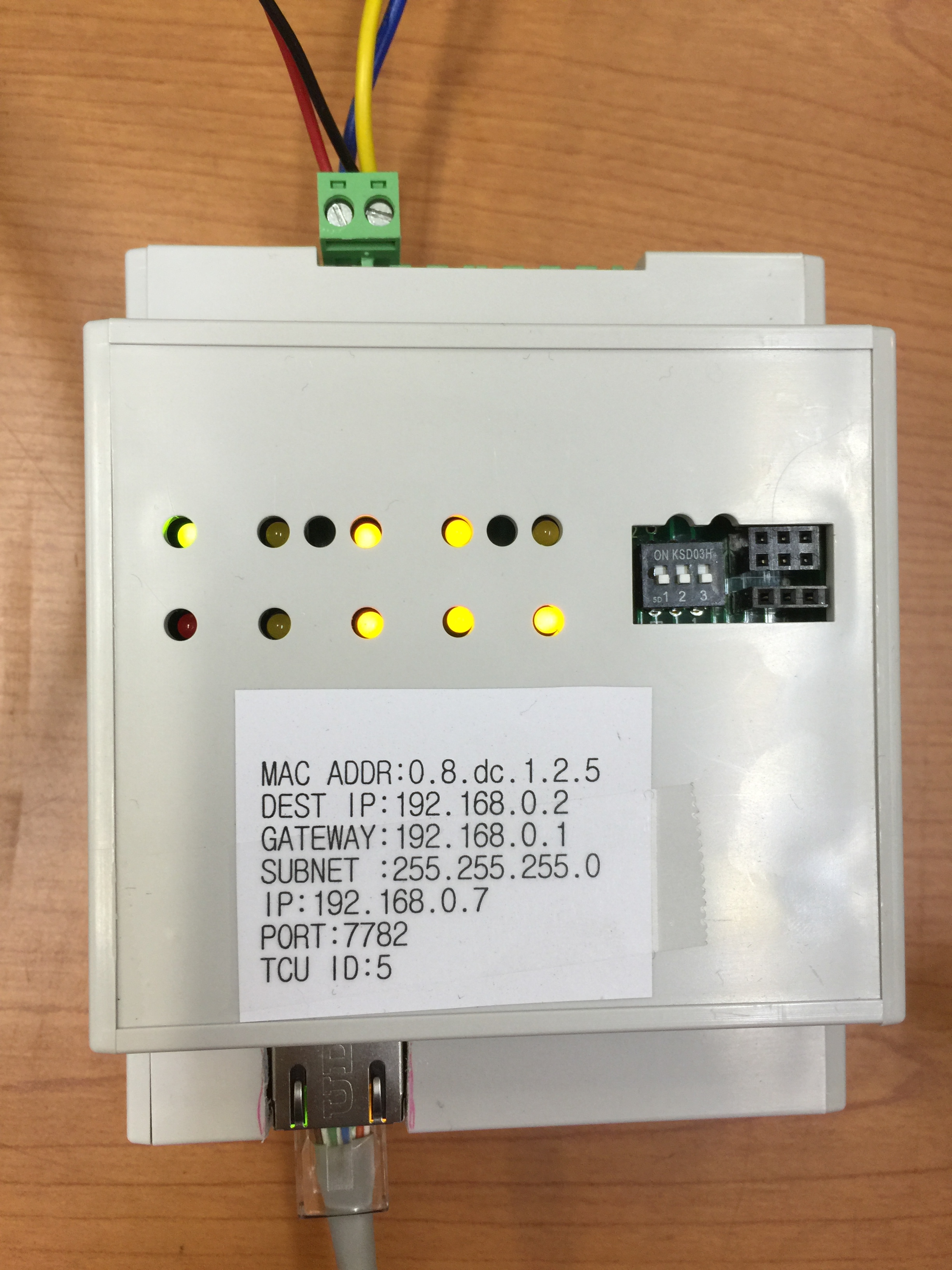 |
| <Figure 4> Appearance of PEMS TCU controller |