PDMS-S Protocol is the driver to communicate with Partial Discharge Monitoring System for SWGR controller of Woo Ri E&C in Korea.
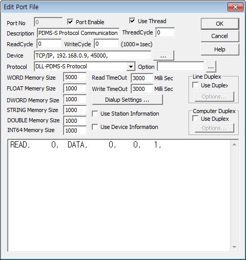
<Figure 1> is read setting example of PDMS-S Protocol communication driver.
|
|
| <Figure 1> Read setting example of PDMS-S Protocol communication driver |
Device part of <Figure 1> input Device Type(TCP/IP), IP address of controller(192.168.0.9 ), service port for TCP(45000) respectively, accordint to the setting of controller.
Read schedule of PDMS-S Protocol communication driver
Read schedule setting parameters are as follows:
1) station – don't care. (fixed to 0)
2) read command – Command : DATA ( refer to <Table 1> ).
3) read start address – don't care.
4) Save start address for Communication Server – Saving start address of Communication Server.
5) Read size – fixed to 1.
Read schedule example)
READ, 0, DATA, 0, 0, 1,
<Table 1> is data saving address and value of PDMS-S Protocol communication driver.
Read command |
Contetns |
Data saving value of Communication Server |
Remarks |
DATA |
Read of current data |
Saving Start Address + 0 : current data 1 Saving Start Address + 1 : current data 2 ...... Saving Start Address + n : current data n |
save each readed byte value to memory |
| <Table 1> Data saving address and value of PDMS-S Protocol communication driver | |||
PDMS-S Protocol communication driver store the same data in WORD, DWORD, FLOAT, DOUBLE memory, but the data format are different.
If you click the icon ![]() in protocol option part at
<Figure 1>, you
can see the dialog box such as <Figure 2>. you can also set read schedule by
using this part.
in protocol option part at
<Figure 1>, you
can see the dialog box such as <Figure 2>. you can also set read schedule by
using this part.
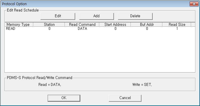 |
| <Figure 2> Example of PDMS-S Protocol communication driver’s Option dialog box |
You can set read schedule by using
![]() ,
,
![]() ,
,
![]() button and listbox of <Figure
2>.
button and listbox of <Figure
2>.
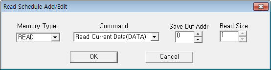 |
| <Figure 3> Example of PDMS-S Protocol communication driver’s read schedule Add/Edit dialog box |
When you click Add button or Edit button in dialogue box of <Figure 2>, dialogue box of <Figure 3> is shown.
You can set setting value by using 'write settings'.
Digital Write
Digital write and analog write have the same setting parameters except output value.
Analog Write
Analog write setting parameters are as follows:
1) PORT Port no. (0 ~ 255)
2) STATION don't care.
3) ADDRESS 0 ~ 100 THD setting value.
4) Extra1 write command : SET.
5) Extra2 0 ~ 31 input signal amplification value. ( default = 0)
6) Output value 1 ~ 99 event level. ( 50 = alarm more than 50% )
Write example 1)
PORT : 0 STATION : 0 ADDRESS : 0 EXTRA1 : SET EXTRA2 : 0
The setting parameter shown above is event level setting example. ( setting value : 1 ~ 99 level )
<Figure 4> shows the appearance of PDMS-S controller.
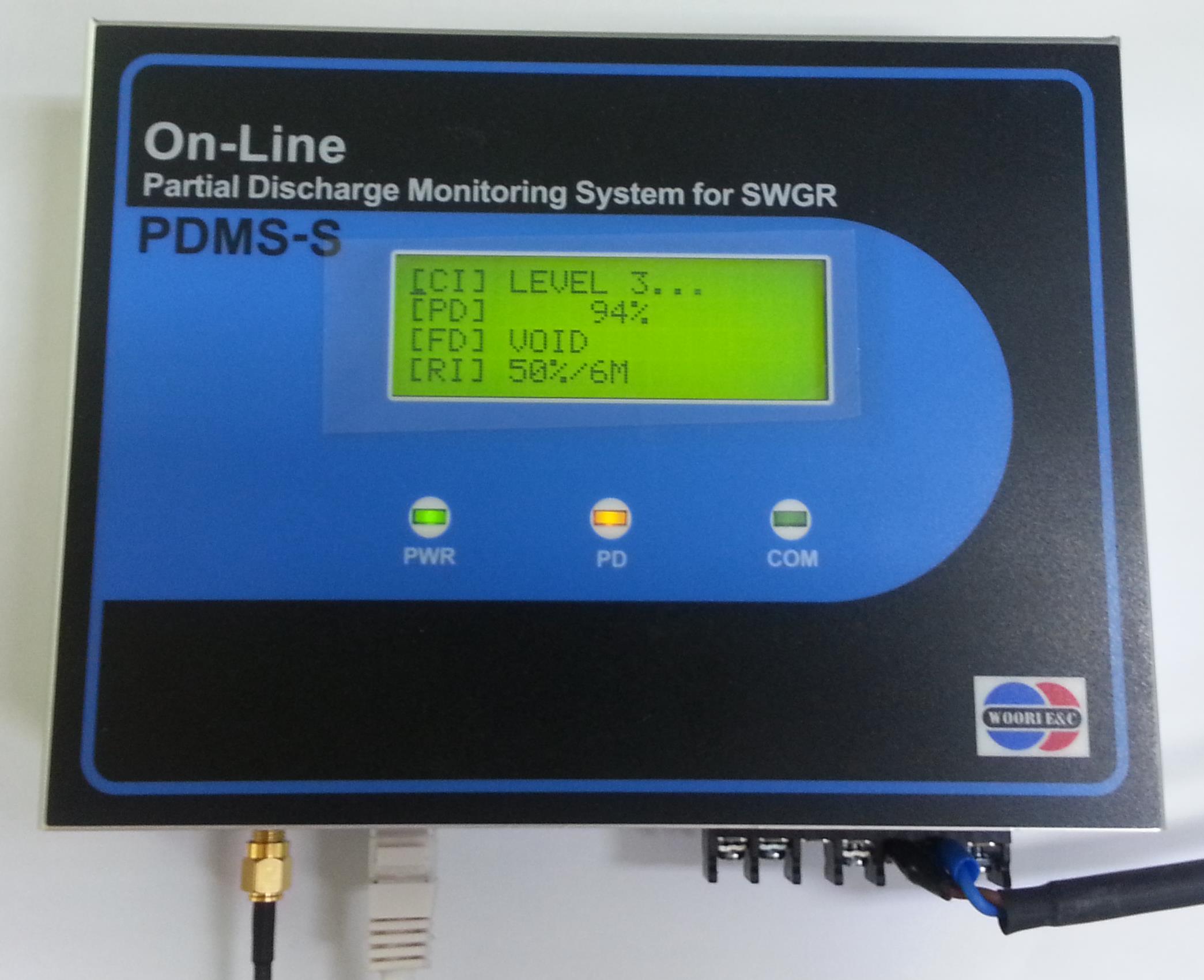 |
| <Figure 4> Appearance of PDMS-S controller |