LS Remote Metering communication driver is the driver to communicate with HCU remote metering controller of LSIS Co., Ltd. in Korea.
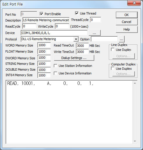
<Figure 1> is read setting example of LS Remote Metering communication driver.
|
|
| <Figure 1> Read setting example of LS Remote Metering communication driver |
Device part of <Figure 1> input Com Port(COM1), Baud Rate(38400), Parity Bit(0), Data Bit(8), Stop Bit(1) respectively, according to setting of controller.
LS Remote Metering communication driver read schedule
Read schedule setting parameters are as follows:
1) Controller ID – 0 ~ 99999 HCU controller ID.
2) Read command – command = A, 1, 2, 3, 4, 5, 6.
A = read of total channel data,
1 ~ 6 = read of eachannel data.
3) Read start address – don't care.
4) Save start address for Communication Server – Saving start address of Communication Server.
5) Read size – fixed to 1. ( refer to <Table 1> )
Read schedule example)
READ, 10001, A, 0, 0, 1,
<Table 1> is data saving address and contents for A read command.
| Data saving address | Contents | Remarks |
| Start addr + 0 | channel 1 data value | 9 digit number value ( decimal unut ) |
| Start addr + 1 | channel 2 data value | |
| Start addr + 2 | channel 3 data value | |
| Start addr + 3 | channel 4 data value | |
| Start addr + 4 | channel 5 data value | |
| Start addr + 5 | channel 6 data value | |
| <Table 1> Data saving address and contents for A read command | ||
LS Remote Metering communication driver store the same data in WORD, DWORD, FLOAT, DOUBLE memory, but the data format are different.
If you click the icon ![]() in protocol option part at
<Figure 1>, you
can see the dialog box such as <Figure 2>. you can also set read schedule by
using this part.
in protocol option part at
<Figure 1>, you
can see the dialog box such as <Figure 2>. you can also set read schedule by
using this part.
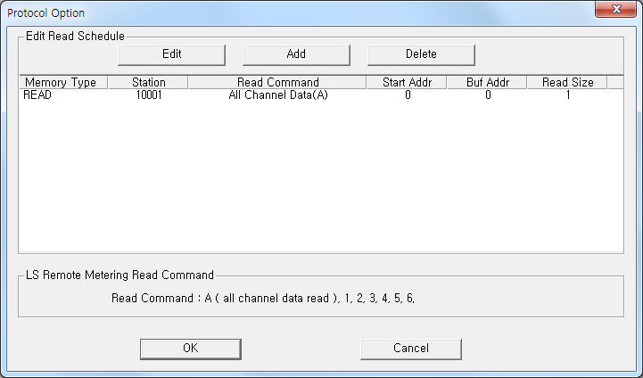 |
| <Figure 2> Example of LS Remote Metering communication driver’s Option dialog box |
You can set read schedule by using ![]() ,
, ![]() ,
, ![]() button and listbox of <Figure
2>.
button and listbox of <Figure
2>.
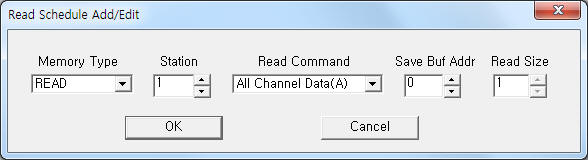 |
| <Figure 3> Example of LS Remote Metering communication driver’s read schedule Add/Edit dialog box |
When you click Add button or Edit button in dialogue box of <Figure 2>, dialogue box of <Figure 3> is shown.
LS Remote Metering communication driver don't support 'Write settings'.
Connection of main power and communication cable are as follows.
Connection of main power
Please connect main power to P0, P1, P2, P3 and connect WHM COM cable to HCU controller such as <Figure 4>.
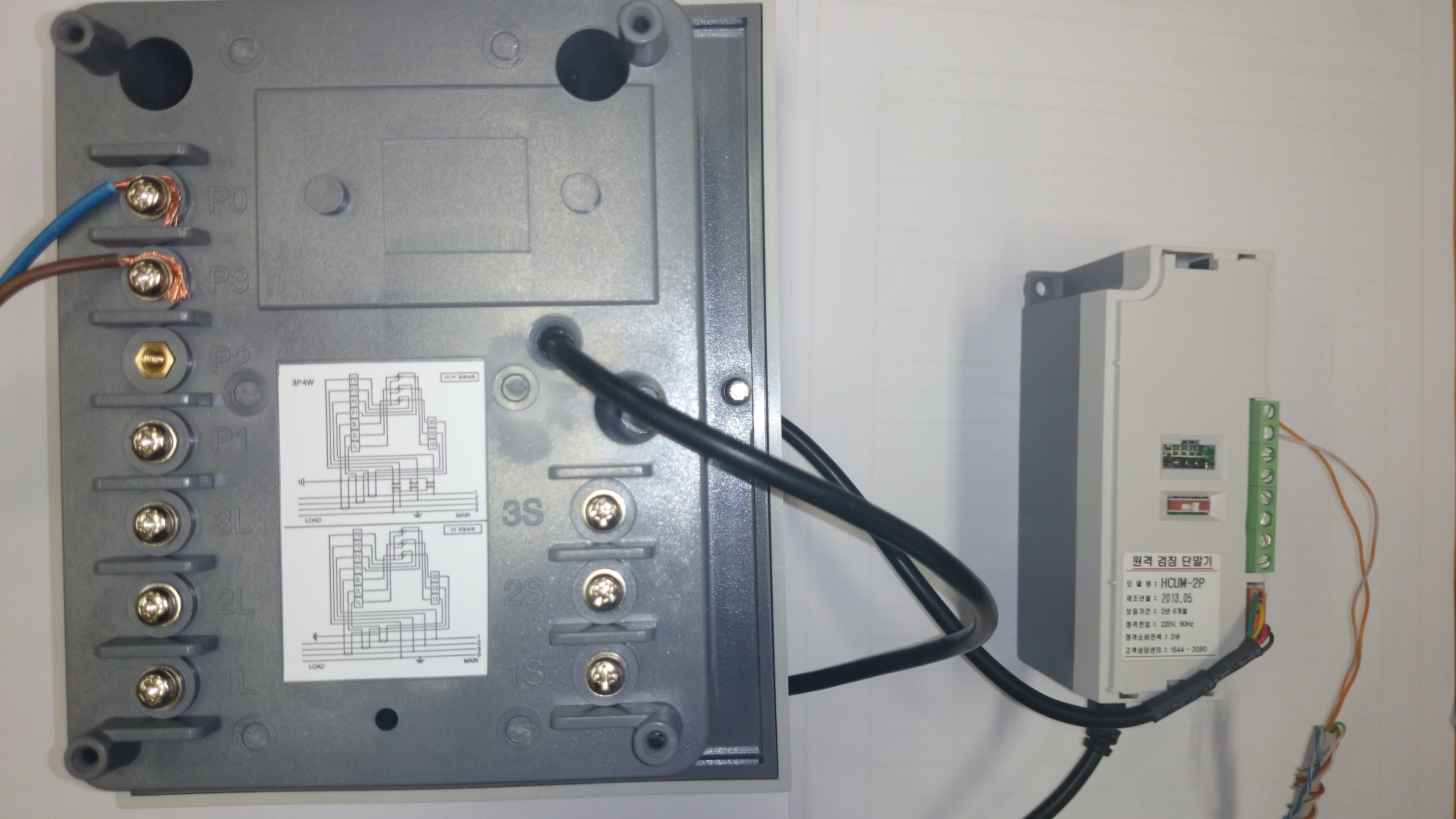 |
| <Figure 4> Connection example of communication cable and main power to LS Remote metering controller |
Connection of communication cable
Please connect RS-485 communication cable to HCU controller such as <Figure 4>.
<Figure 5> is appearance of LS Remote Power Meter controller.
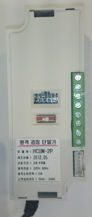
<Figure 6> is appearance of LS Remote Metering HCU controller.
Note) HCU controller has different measuring and RS-485 connector for each model. So, you should check RS-485 connector.
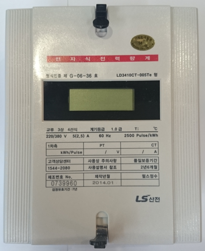 |
| <Figure 5> Appearance of LS Remote Power Meter controller |
 |
|
<Figure 6> Appearance of LS Remote Metering HCU controller |