KEP SuperTrol II is the driver to communicate with SuperTrol II multifunction flow computer of Kessler-Ellis Products in U.S.A.
<Figure 1> is read setting example of KEP SuperTrol II communication driver.
|
|
| <Figure 1> Read setting example of KEP SuperTrol II communication driver |
Device part of <Figure 1> input com port(COM4), baud rate(9600), parity bit(0), data bit(8), stop bit(1) respectively, accordint to the setting of flow computer.
Also, you can set 'waiting time after write command'(0 ~ 3000 mSec, default : 500) at Option part.
Read schedule of KEP SuperTrol II communication driver
Read schedule setting parameters are as follows:
1) station – 0 ~ 99 station ID.
2) read group number – 0 ~ 99 group number.(refer to Chapter 3)
3) read address – 0 ~ 99 address.(refer to Chapter 3)
4) Save start address for Communication Server – Saving start address of Communication Server.
5) Read size – fixed to 1.
Read schedule example)
READ, 1, 00, 0, 0, 1,
READ, 1, 00, 1, 1, 1,
READ, 1, 00, 2, 2, 1,
READ, 1, 01, 0, 3, 1,
READ, 1, 01, 1, 4, 1,
READ, 1, 01, 2, 5, 1,
READ,
1, 02, 0, 6, 1,
READ, 1, 02, 1, 7, 1,
READ, 1, 02, 2, 8, 1,
KEP SuperTrol II communication driver store the same data in WORD, DWORD, FLOAT, DOUBLE, INT64 memory, but the data format are different.
If you click the icon ![]() in protocol option part at
<Figure 1>, you
can see the dialog box such as <Figure 2>. you can also set read schedule by
using this part.
in protocol option part at
<Figure 1>, you
can see the dialog box such as <Figure 2>. you can also set read schedule by
using this part.
 |
| <Figure 2> Example of KEP SuperTrol II communication driver’s Option dialog box |
You can set read schedule by using
![]() ,
,
![]() ,
,
![]() button and listbox of <Figure
2>.
button and listbox of <Figure
2>.
 |
| <Figure 3> Example of KEP SuperTrol II communication driver’s read schedule Add/Edit dialog box |
When you click Add button or Edit button in dialogue box of <Figure 2>, dialogue box of <Figure 3> is shown.
You can set setting value by using 'write settings'.
Digital Write
Digital write and analog write have the same setting parameters except output value.
Analog Write
Analog write setting parameters are as follows:
1) PORT Port no. (0 ~ 255)
2) STATION 0 ~ 99 station ID.
3) ADDRESS 0 ~ 99 address.(refer to Chapter 3)
4) Extra1 0 ~ 99 group number.(refer to Chapter 3)
5) Extra2 don't care.
Write example 1)
PORT : 0 STATION : 1 ADDRESS : 0001 EXTRA1 : 2 EXTRA2 : 0
The setting parameter shown above is Heat Flow Units(Group = 2, Address = 1, output value = 0 ~ 8) setting example for 1 flow computer ID.
Write example 2)
PORT : 0 STATION : 1 ADDRESS : 0000 EXTRA1 : 3 EXTRA2 : 0
The setting parameter shown above is Instrument Function(Group = 3, Address = 0, output value = 0 ~ 2) setting example for 1 flow computer ID.
<Figure 4> is main Group/Address and contents of KEP SuperTrol II flow computer.
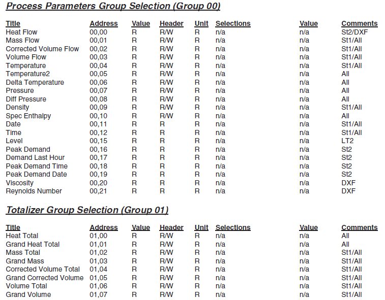 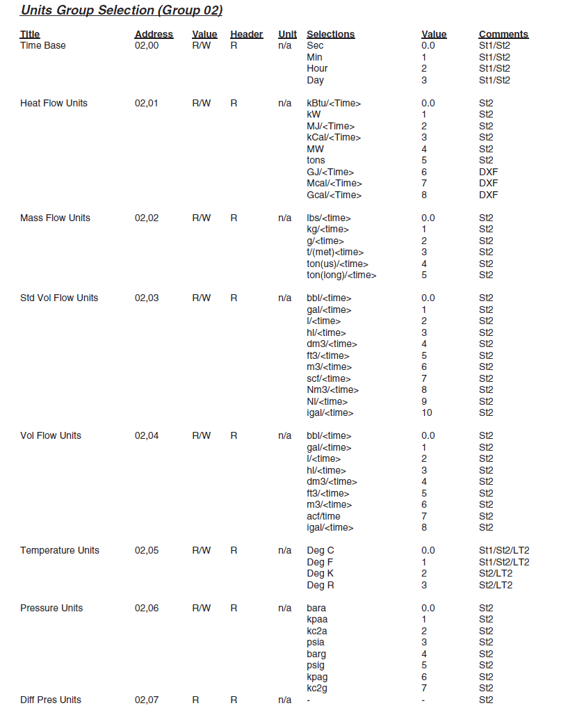 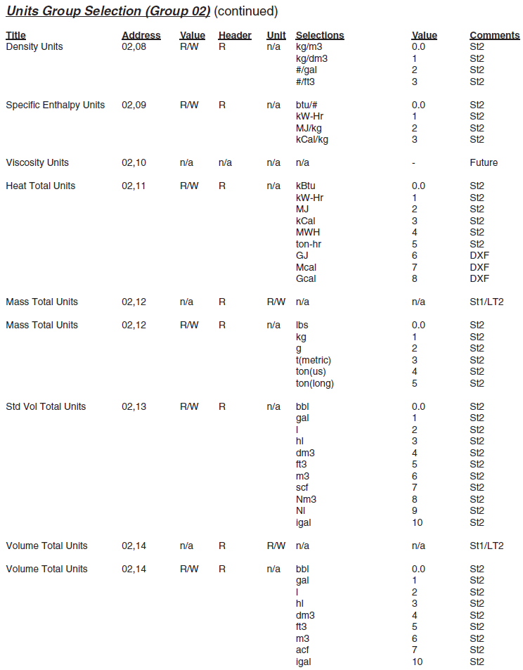 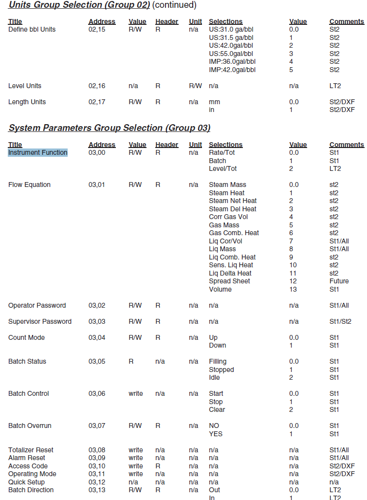 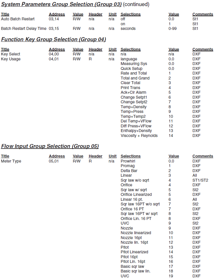 |
| <Figure 4> Main Group/Address and contents of KEP SuperTrol II flow computer |
<Figure 5> shows the appearance of KEP SuperTrol II flow computer.
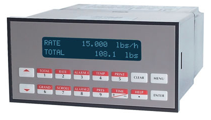 |
| <Figure 5> Appearance of KEP SuperTrol II flow computer |