GMPC II communication driver is the driver to communicate with power meter GIMAC/GIMACII/GIMACIII/uRTU(or uRTU II) model of LSIS Co., Ltd. in Korea.
uRTU or uRTU II model communicate with GMPC controller( GMPC I, GMPC II, GMPC III, GMPC V, ... ) and computer read and write GMPC's data.
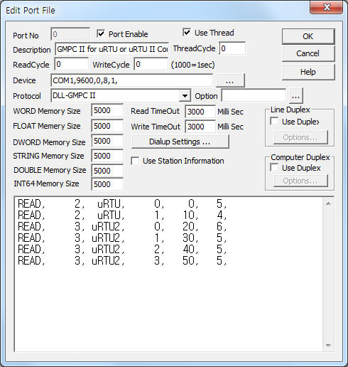
<Figure 1> is read setting example of GMPC II communication driver for uRTU model.
|
|
| <Figure 1> Read setting example of GMPC II communication driver for uRTU model |
Device part of <Figure 1> input Com Port(COM1 or TCP/IP, UDP/IP, etc), Baud Rate(9600), Parity Bit(0), Data Bit(8), Stop Bit(1) respectively according to setting of GMPC.
Baud rate, parity bit, data bit, stop bit can set by using switch of rear or front panel(GMPC controller).
GMPC II communication driver read schedule for uRTU or uRTU II
Read schedule setting parameters are as follows:
1) STATION – uRTU or uRTU II controller station number = 0 ~ 255.
2) Controller Model – Model = uRTU or uRTU2 (when using uRTU, uRTU II model).
3) Read data type – Data type = 0, 1, 2, 3, 4, 5.... ( Cmd - 10h, refer to reference manual of uRTU )
4) Save Start Address for Communication Server – saveing start address of Communication Server.
5) Read Size – Read size. Fixed according to read data type. ( Refer to <Table 1> ~ <Table 2> )
6) Sub1 command - Input Sub1 command according to controller model.
7) Sub2 command - Input Sub 2 command according to controller model.
Read schedule example)
READ, 2, uRTU, 0, 0, 5,
READ, 2, uRTU, 1, 10, 4,
READ, 3, uRTU2, 0, 20, 6,
READ, 3, uRTU2, 1, 30, 5,
READ, 3, uRTU2, 2, 40, 5,
READ, 3, uRTU2, 3, 50, 5,
<Table 1>, <Table 2> are data type and contents for uRTU, uRTU II model.
<Table 3> ~ <Table 6> are data saving address and contents of '0' ~ '3' data type for uRTU II.
| Data type | Contents | Data format | Data size | Remarks |
| 0 | Contact input/output & Count | BYTE/WORD | 5 | 3 BYTE contact input/output, 2 WORD Count value |
| 1 | Analog input value | WORD | 4 | |
| <Table 1> Data type and contents for uRTU model | ||||
| Data type | Contents | Data format | Data size | Remarks |
| 0 | Status value of contact input/putput | BYTE | 6 | Refer to <Table 3> |
| 1 | Coefficient value | WORD | 5 | Refer to <Table 4> |
| 2 | Analog input current | WORD | 5 | Refer to <Table 5> |
| 3 | Analog input current | WORD | 5 | Refer to <Table 6> |
| <Table 2> Data type and contents for uRTU II model | ||||
| Data Saving Address | Contents | Point | Remarks |
| 0 | I/O Type | 0 : NONE, 1 : DI16, 2 : AI8, 3 : AI8DO8 | |
| 1 | Input status 1 | DIN07 ~ DIN00 | |
| 2 | Input status 2 | DIN17 ~ DIN10 | |
| 3 | Input status 3 | DIN27 ~ DIN20 | use only when I/O Type = 1 |
| 4 | Input status 4 | DIN37 ~ DIN30 | use only when I/O Type = 1 |
| 5 | Output status | DOUT07 ~ DOUT00 | use only when I/O Type = 31 |
| <Table 3> Data saving address and contents of '0' data type for uRTU II | |||
| Data Saving Address | Contents | Point | Remarks |
| Start Add + 0 | I/O Type | 0 : NONE, 1 : DI16, 2 : AI8, 3 : AI8DO8 | |
| Start Add + 1 ~ 4 | Coefficient value 1 ~ 4 | DIN04 ~ DIN07 Count | |
| <Table 4> Data saving address and contents of '1' data type for uRTU II | |||
| Data Saving Address | Contents | Point | Remarks |
| Start Add + 0 | I/O Type | 2 : AI8, 3 : AI8DO8 | |
| Start Add + 1 ~ 4 | Analog input current information 1 ~ 4 | AIN00 ~ AIN03 | use only when I/O Type = 2 or 3 ratio of 4~20mA, data = 0~8000 |
| <Table 5> Data saving address and contents of '2' data type for uRTU II | |||
| Data Saving Address | Contents | Point | Remarks |
| Start Add + 0 | I/O Type | 2 : AI8, 3 : AI8DO8 | |
| Start Add + 1 ~ 4 | Analog input current information 5 ~ 8 | AIN04 ~ AIN07 | use only when I/O Type = 2 or 3 ratio of 4~20mA, data = 0~8000 |
| <Table 6> Data saving address and contents of '3' data type for uRTU II | |||
You can write uRTU equipment's setting value by using write settings.
Note) Write for uRTU can control when the equipment's setting is 'remote'.
Digital Write
Digital write setting parameters are as follows:
1) PORT Port no. (0 ~ 255)
2) STATION uRTU controller station number = 0 ~ 255.
3) ADDRESS Control command number(hex-decimal unit), refer to <Table 7>.
Model(EXTRA1) = uRTU.
0000 ~ 000F – digital output 0 Bit ~ F Bit,
EXTRA2 : 0 = ON/OFF control, 1 : 2000 mSec pulse output.
Model(EXTRA1) = uRTU2.
0000 ~ 0007 – digital output 0 Bit ~ 7 Bit.
EXTRA2 : 0 = ON/OFF control, 1 : 2000 mSec pulse output, 2 : 1000 mSec pulse output, 3 : 1500 mSec pulse output, 4 : 2000 mSec pulse output.
0008 ~ 000B – Coefficient value remote Clear, 적산 point 1 ~ 4.
000F – all Coefficient value remote Clear.
4) Extra1 Model name.
uRTU – uRTU,
uRTU2 – uRTU II.
5) Extra2 Selection of normal or pulse output, refer to <Table 7>.
Value of Extra2 |
Contents |
Pulse time |
0 |
ON/OFF control |
- |
1 |
Pulse control |
500 mSec |
2 |
1000 mSec (1 second) |
|
3 |
1500 mSec |
|
4 |
2000 mSec (2 second) |
|
| <Table 7> Write control type according to Extra2 for uRTU II model | ||
Write example 1)
PORT : 0 Station : 7, ADDRESS : 0000, EXTRA1 : uRTU2, EXTRA2 : 0
The setting parameter shown above is a digital control example for 0(1st) digital output. ( 7 controller station uRTU II )
Write example 2)
PORT : 0 Station : 8, ADDRESS : 0003, EXTRA1 : uRTU, EXTRA2 : 0
The setting parameter shown above is a digital control example for 3(4th) digital output. ( 8 controller station uRTU )
Write example 3)
PORT : 0 Station : 7, ADDRESS : 0001, EXTRA1 : uRTU2, EXTRA2 : 2
The setting parameter shown above is a digital control example for 1(2nd) digital output with 1000 mSec pulse time. ( 7 controller station uRTU II )
Write example 2)
PORT : 0 Station : 8, ADDRESS : 0002, EXTRA1 : uRTU, EXTRA2 : 1
The setting parameter shown above is a digital control example for 2(3rd) digital output with 2000 mSec pulse time. ( 8 controller station uRTU )
Analog Write
GMPC II communication driver for uRTU model don't support analog write.