GE Ethernet communication driver is the driver to communicate(ethernet) with PLC of GE Fanuc Automation in U.S.A.
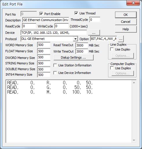
<Figure 1> is read setting example of GE Ethernet communication driver.
|
|
| <Figure 1> Read setting example of GE Ethernet communication driver |
Device part of <Figure 1> input Device type(TCP/IP), IP address of PLC(192.168.1.101), service port of TCP/IP protocol (fixed to 18245 ),respectively, according to setting of PLC.
Also you can set 'readed data saving method for Bit memory'( BIT : decimal unit, 0, blank, etc : hexadecimal unit, default = 0), PLC model( 0 - 9000 series, PAC - PAC System, default = 0), Ethernet slot position for PAC System( 0 - 15, default = 1), whether to use 'address - 1' when Digital write( 0 - use, NB_ADDR - don't use,default = 0), whether to use 'address - 1' when Analog write( 0 - use, NW_ADDR - don't use,default = 0) by using option part.
GE Ehternet communication driver read schedule
Read schedule setting parameters are as follows:
1) STATION – Don't care.
2) Read command – Memory type of PLC = R, RF, RF2, AI, AQ, I, Q, T, M, SA, SB, SC, S, G. ( refer to <Table 1> )
3) Read start addresst – Read start address of PLC memory.
4) Save Start Address for Communication Server – saveing start address of Communication Server.
5) Read Size – Read size. ( 1 ~ 450 )
Read schedule example)
READ, 0, R, 0, 0, 50,
READ, 0, G, 0, 50, 50,
READ, 0, M, 0, 100, 10,
READ, 0, RF, 50, 0, 1,
READ, 0, RF2, 100, 0, 1,
<Table 1> is memory type and contents of GE PLC.
Memory type |
Contents |
Data unit |
R RF RF2 |
Register area |
WORD RF, RF2 = float unit |
AI |
Analog input |
|
AQ |
Analog output |
|
I |
Digital input |
BYTE, BIT |
Q |
Digital output |
|
T |
Discrete Temporaries |
|
M |
Discrete Internals |
|
SA, SB, SC |
Discretes |
|
S |
Discretes |
|
G |
Genus Global Data |
|
| <Table 1> Memory type and contents of GE PLC | ||
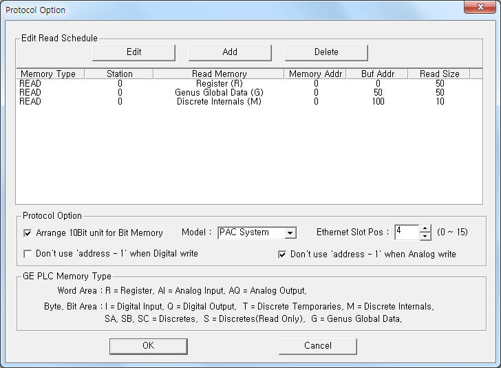
If you click the icon ![]() in protocol option part at
<Figure 1>, you
can see the dialog box such as <Figure 2>. you can also set read schedule by
using this part.
in protocol option part at
<Figure 1>, you
can see the dialog box such as <Figure 2>. you can also set read schedule by
using this part.
 |
|
<Figure 2> Example of GE Ehternet communication driver’s Option dialog box |
You can set read schedule by using
![]() ,
,
![]() ,
,
![]() button and listbox of <Figure
2>.
button and listbox of <Figure
2>.
Readed data saving method for Bit memory, PLC model, Ethernet slot position for PAC System, whether to use 'address - 1' when Digital write, whether to use 'address - 1' when Analog write can set by using of Protocol Option part in <Figure 2>.
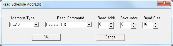 |
| <Figure 3> Example of GE Ehternet communication driver’s read schedule Add/Edit dialog box |
When you click Add button or Edit button in dialogue box of <Figure 2>, dialogue box of <Figure 3> is shown.
You can change the value of device memory by using write settings.
Digital Write
Digital write setting parameters are as follows:
1) PORT Port no. (0 ~ 255)
2) STATION Don't care.
3) ADDRESS Write addres in memory type.
when using 'address - 1' for Digital write at option : Address - 1,
when don't using 'address - 1' for Digital write at option : Address.
4) Extra1 Write memory type = I, Q, T, M, SA, SB, SC, G.
5) Extra2 Don't care.
Write example 1)
PORT:0, station:0, ADDRESS:0001, Extra1: Q, Extra2 :
The setting parameter shown above is a bit write(On/Off) example of 0001(1st bit address) in the Q device memory.
Analog Write
Analog write setting parameters are as follows:
1) PORT Port no. (0 ~ 255)
2) STATION Don't care.
3) ADDRESS Write addres in memory type.
when using 'address - 1' for Analog write at option : Address - 1,
when don't using 'address - 1' for Analog write at option : Address.
4) Extra1 Write memory type = R, RF, RF2, AI, AQ, I, Q, T, M, SA, SB, SC, G.
5) Extra2 Don't care.
Write example 1)
PORT:0, station:0, ADDRESS:0005, Extra1: R, Extra2 :
The setting parameter shown above is an analog write example of 0005(5th word address) word in the R device memory.
Write example 2)
PORT:0, station:0, ADDRESS:0150, Extra1: RF, Extra2 :
The setting parameter shown above is an analog write example of 300 + 301(300th + 301th word address) float in the R device memory.
Write example 3)
PORT:0, station:0, ADDRESS:0300, Extra1: RF2, Extra2 :
The setting parameter shown above is an analog write example of 300 + 301(300th + 301th word address) float in the R device memory.
<Figure 4> shows the appearance of GE PAC System PLC.
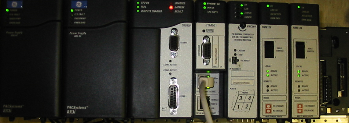 |
| <Figure 4> Appearance of GE PAC System PLC |