iGrow 1400 communication driver is the driver to communicate with controller(for measuring temperature, humidity, wind direction, wind speed, rainfall, ...) of Link4 Corporation in U.S.A.
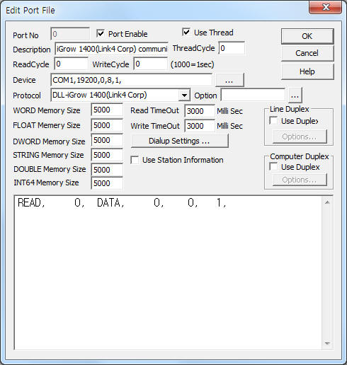
<Figure 1> is read setting example of iGrow 1400(Link4 Corp) communication driver.
 |
| <Figure 1> Read setting example of iGrow 1400(Link4 Corp) communication driver |
Device part of <Figure 1> input Com Port(COM1), Baud Rate(19200), Parity Bit(0), Data Bit(8), Stop Bit(1) respectively, according to controller.
iGrow 1400(Link4 Corp) communication driver read schedule
Read schedule setting parameters are as follows:
1) Station – 0 ~ 31 station number. default = 0.
2) Read command – Fixed to DATA.
3) Read Start Address – Don't care(fixed to 0).
4) Save start address for Communication Server – Saving start address of Communication Server. ( refer to <Table 1> )
5) Read Size – Fixed to 1.
6) Saving method for reading data – 0 = normal method( refer to <Table 1> ), 1 ~ 255 = read at work folder\SCAN\CH_INFO%03d.ini file for data saving method. ( refer to <Table 2> )
Read schedule example)
READ, 0, DATA, 0, 0, 1,
<Table 1> is data saving address and contents of iGrow 1400(Link4 Corp) communication driver.
<Table 2> is 'ini' file input method for data saving method.
| Data Saving Address | Contents | Data type | Range |
| Start Add + 0 | In Temp | Float |
|
| Start Add + 1 | Out Temp | ||
| Start Add + 2 | Humidity | WORD | 0 ~ 99 |
| Start Add + 3 | Co2 | 0 ~ 4999 |
|
| Start Add + 4 | - |
|
|
| Start Add + 5 | Amount of sunshine | 0 ~ |
|
| Start Add + 6 | Wind speed(MPH) | 0 ~ |
|
| Start Add + 7 | Wind direction | BYTE | 0 ~ 1 = N, 8 ~ 9 = S, 2 ~ 3 = NE, A ~ B = SW, 4 ~ 5 = E, C ~ D = W, 6 ~ 7 = SE, E ~ F = NW |
| Start Add + 8 | Rainfall | 0 = OFF, 1 = rainfall |
|
| Start Add + 9 | Backup Sensor | Float |
|
| Start Add + 10~14 | BHeat1 ~ BHeat5 |
|
|
| Start Add + 15 | Heater Set Point |
|
|
| Start Add + 16 | Cooler Set Point |
|
|
| Start Add + 17 | Humidity Set Point | WORD |
|
| Start Add + 18 | DeHumidity Set Point |
|
|
| Start Add + 19 | Temp Stage |
|
|
| Start Add + 20 | Humidity Stage |
|
|
| Start Add + 21 | - | WORD | - |
| Start Add + 22 | - | BYTE | - |
| Start Add + 23 ~ 28 | Current year, month, day, hour, minute, second | data, time |
|
| <Table 1> Data saving address and contents of iGrow 1400(Link4 Corp) communication driver | |||
Filename |
Input method of 'ini' file |
work folder\SCAN\CH_INFO%03d.ini
%03d = 1 ~ 255 data number |
1) Input text at 1st line of file. 2) Separate by comma( , ) each element. 3) Input 1 ~ 256 channel data. 4) B = Byte, W = Word, D = Double Word, F = Float, S = String, T = Date/Time (Double Word). 5) S?? : ?? = string length. Example) S10 : string length = 10 |
| <Table 2> 'ini' file input method for data saving method | |
<Figure 2> is setting example of 'ini' file for data saving method.
 |
| <Figure 2> Setting example of 'ini' file for data saving method |
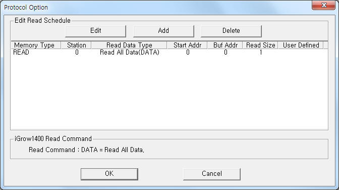
If you click the icon ![]() in protocol option part, you
can see the dialogue box such as <Figure 3>. you can also set read schedule by
using this part.
in protocol option part, you
can see the dialogue box such as <Figure 3>. you can also set read schedule by
using this part.
 |
| <Figure 3> Example of iGrow 1400(Link4 Corp) communication driverí»s Option dialog box |
You can set read schedule by using ![]() ,
, ![]() ,
, ![]() button and listbox of <Figure
3>.
button and listbox of <Figure
3>.
 |
| <Figure 4> Example of iGrow 1400(Link4 Corp) communication driverí»s read schedule Add/Edit dialog box |
When you click Add button or Edit button in dialogue box of <Figure 3>, dialogue box of <Figure 4> is shown.
iGrow 1400(Link4 Corp) communication driver don't support 'writing settings'.
Please connect RS-232C communication cable(cross) to TX, RX, GND connector of iGrow 1400(Link4 Corp) Controller such as <Figure 5>.
Computer side iGrow 1400 side
RX ------------------------ TX
TX ------------------------ RX
GND ------------------------ GND
<Figure 5> is connection example of communication cable to iGrow 1400 Controller.
<Figure 6> is appearance of iGrow 1400 controller.
 |
| <Figure 5> Connection example of communication cable to iGrow 1400 Controller |
 |
| <Figure 5> Appearance of iGrow 1400 controller |