iGCP10 Digital Control communication driver is the driver to communicate with power meter controller of K2 Power Co., Ltd. in Korea.
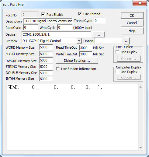
<Figure 1> is read setting example of iGCP10 Digital Control communication driver.
 |
| <Figure 1> Read setting example of iGCP10 Digital Control communication driver |
Device part of <Figure 1> input Com Port(COM1), Baud Rate(9600), Parity Bit(2), Data Bit(8), Stop Bit(1) respectively, according to controller.
iGCP10 Digital Control communication driver read schedule
Read schedule setting parameters are as follows:
1) Station – Don't care.
2) Read command – Don't care(fixed to 0).
3) Read Start Address – Don't care(fixed to 0).
4) Save start address for Communication Server – Saving start address of Communication Server. ( refer to <Table 1> )
5) Read Size – Fixed to 1.
Read schedule example)
READ, 0 , 0, 0, 0, 1,
<Table 1> is data saving address and contents of iGCP10 Digital Control communication driver.
<Table 2> is status and warning error for each bit position.
Data Saving Address |
Contents |
Remarks |
Start Add + 0 ~ 2 |
R, S, T voltage |
|
Start Add + 3 |
Frequency |
|
Start Add + 4 ~ 6 |
R, S, T current |
|
Start Add + 7 |
power ( KW ) |
|
Start Add + 8 |
Power Factor |
|
Start Add + 9 |
Battery voltage |
|
Start Add + 10 |
RPM |
|
Start Add + 11 |
Cool Temp |
|
Start Add + 12 |
Oil pressure |
|
Start Add + 13 |
Fuel Level |
|
Start Add + 14 ~ 15 |
Reserved |
|
Start Add + 16 |
KW Hours |
double word value |
Start Add + 17 |
Running Hours |
|
Start Add + 18 |
Status (status value) |
refer to <Table 2> |
Start Add + 19 |
Warning Error |
|
Start Add + 20 |
Shutdown Error |
|
Start Add + 21 |
Option |
|
| <Table 1> Data saving address and contents of iGCP10 Digital Control communication driver | ||
Bit position |
Status (status value) |
Warning Error |
Shutdown Error |
0 |
Alarm |
Cool Send |
Low Oil |
1 |
Pre Alarm |
Low Cool |
High Cool |
2 |
Not Auto |
Low Fuel |
Fail2 Start |
3 |
Remote |
High Bat |
Over Speed |
4 |
Running |
Low Bat |
EMG Stop |
5 |
Emergency |
Over Load |
Over Volt |
6 |
ATS
|
Oil Send |
Under Volt |
7 |
ATS Gen |
MPU Send |
Over Amp |
8 |
ATS Trip |
Low Oil |
OCGR Stop |
9 |
U Lead |
High Cool |
|
10 |
V Lead |
Bat Fail |
|
11 |
W Lead |
GCB Aux |
|
12 |
CT Enable |
ATS Aux |
|
13 |
OP Enable |
|
|
14 |
Bus On |
|
|
15 |
Reserved |
|
|
| <Table 2> Status and warning error for each bit position | |||
You can control(Run, Stop, ... ) iGCP10 controller by using write settings.
Digital Write
Digital write and analog write have the same setting parameters except output value(0 or 1).
Analog Write
Analog write setting parameters are as follows:
1) PORT Port no. (0 ~ 255)
2) STATION Don't care(fixed to 0).
3) ADDRESS Don't care(fixed to 0).
4) Extra1 Write command.
MANU : Manual Run,
AUTO : Auto Run,
STOP : Engine Stop,
CLOSE : GCB Close,
TRIP : GCB Trip,
RESET : Alarm Reset.
5) Extra2 Don't care.
Write example 1)
PORT:0, station:0, ADDRESS:0000, Extra1: MANU, Extra2 :
The setting parameter shown above is 'Manual Run' control example.
Write example 2)
PORT:0, station:0, ADDRESS:0000, Extra1: AUTO, Extra2 :
The setting parameter shown above is a 'Auto Run' control example.
Write example 3)
PORT:0, station:0, ADDRESS:0000, Extra1: STOP, Extra2 :
The setting parameter shown above is a 'Engine Stop' control example.
Write example 4)
PORT:0, station:0, ADDRESS:0000, Extra1: CLOSE, Extra2 :
The setting parameter shown above is a 'GCB Close' control example.
Connection of main power line and communication cable are as follows.
Connection of main power
Please connect 8 ~ 32V DC main power to 1VDC+, 2VDC- connector such as <Figure 2>.
Connection of communication cable
Please connect normal RS-232C communication cable(cross) to 9 pin connector of iGCP10 Digital Controller such as <Figure 2>.
<Figure 2> is connection example of main power and communication cable to iGCP10 Digital Controller.
 |
| <Figure 2> Connection example of main power and communication cable to iGCP10 Digital Controller |