ZMD405 Meter(Landis+Gyr) communication driver is the driver to communicate with ZND405 Power Meter.
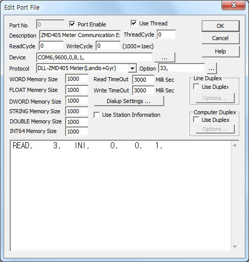
<Figure 1> is read setting example of ZMD405 Meter(Landis+Gyr) communication driver .
|
|
| <Figure 1> Read setting example of ZMD405 Meter(Landis+Gyr) communication driver |
Device Setting of <Figure 1> are input, Com Port(COM6), Com Speed(9600), Parity Bit(0), Data Bit(8), Stop Bit(1).
Also 'PC Address'(0 ~ 255, default = 33) is set by using option part.
ZMD405 Meter(Landis+Gyr) communication driver read schedule
Read schedule setting parameters are as follows:
1) STATION – Equipment ID = 0 ~ 255.
2) Read Command – Command = INI, DATA.(Refer to <Table 1>)
3) Read Start Addres – INI Command = 0 ~ 255 : INI Data File Number,
DATA = 0000h ~ FFFFh(65535) : Data Address.
4) Save Start Address for Communication Server – saveing start address of Communication Server.
5) Read Size – read size = 1.
Read schedule example)
READ, 3, INI, 0, 0, 1,
READ, 3, DATA, B28h, 10, 1,
READ,
3, DATA, 8BC0h, 11, 1,
<Table 1> is a description of read commands type and stored values of ZMD405 Meter(Landis+Gyr) communication driver.
<Table 2> is INI data file input method for multi 'Data Address reading.
| Read Command | Content | Stored Values | Remarks |
| INI | Read of multi data address Stored in the INI Data File | Start Add + 0 : Read content of 1st data address Start Add + 1 : Read content of 2nd data address ... |
Refer to <Table 2> |
| DATA | Data read of 'Data Address' (Start Address) |
Start Add + 0 : Read content of entered 'Data Address' | |
| <Table 1> Read commands type and stored values of ZMD405 Meter(Landis+Gyr) communication driver | |||
| Filename | Method |
work folder\SCAN\R_DATA%03d.ini, %03d = 0 ~ 255 : file number. |
1) You shoud input all 'Data Address' on one line. 2) Each data separate to comma ( , ). 3) Max 'Data Address' = 19. 4) 'Data Address' = 4 digit hexdecimal.
Input Example) 0B28, 8BC0, 8C58, |
| <Table 2> INI data file input method for multi 'Data Address' reading | |
ZMD405 Meter(Landis+Gyr) communication driver store the same data in WORD, DWORD, FLOAT, DOUBLE, INT64 memory, but the data format are different.
If you click the icon
![]() in protocol option part, you can see the dialog box such as <Figure 2>. you can
also set read schedule by using this part.
in protocol option part, you can see the dialog box such as <Figure 2>. you can
also set read schedule by using this part.
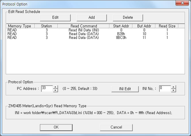 |
| <Figure 2> Example of ZMD405 Meter(Landis+Gyr) Communication Driver’s Option dialog box |
You can set read schedule by using
![]() ,
,
![]() ,
,
![]() button and listbox of <Figure 2>.
button and listbox of <Figure 2>.
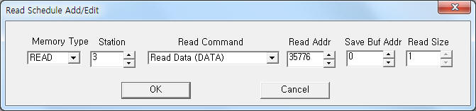 |
| <Figure 3> Example of ZMD405 Meter(Landis+Gyr) communication driver’s read schedule Add/Edit dialog box |
When you click Add button or Edit button in dialog box of <Figure 2>, dialog box of <Figure 3> is shown.
When you click ![]() button after selecting 'INI No.' of <Figure 2>, dialog box of <Figure 4> is
shown.
button after selecting 'INI No.' of <Figure 2>, dialog box of <Figure 4> is
shown.
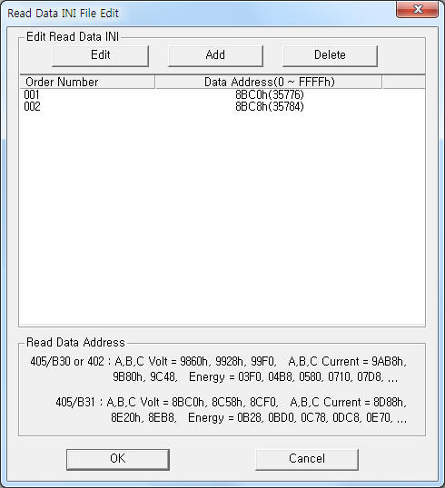 |
| <Figure 4> Example of 'Data Address' input dialog for multi data read |
You can input by using
![]() ,
,
![]() ,
,
![]() button and listbox of <Figure 4>.
button and listbox of <Figure 4>.
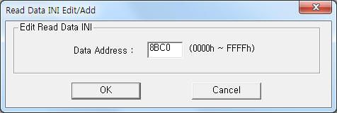 |
| <Figure 5> Example of 'Data Address' Edit/Add dialog |
When you click Add button or Edit button in dialog box of <Figure 4>, dialog box of <Figure 5> is shown.
ZMD405 Meter(Landis+Gyr) communication driver don’t support ‘Write settings’.
You have to connect serial communication cable in the following ways.
Connection of RS-485 communication cable
You must connect RS-485 communication cable to '1(Tx-, Tx-)', '2(Tx+, Rx+)' RJ11 jack of ZMD405 Meter and '+(Tx+, Rx+), -( Tx-, Rx-)' RS-485 terminal of PC Respectively.
<Figure 6> is example of RS-485 communication cable connection to ZMD405 Meter.
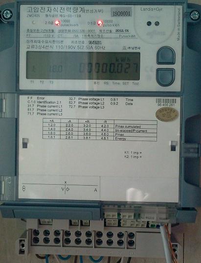 |
| <Figure 6> Example of RS-485 communication cable connection to ZMD405 Meter |