YOKOGAWA UT Series(550 etc) communication driver is the driver to communicate with UT series PID controller of Yokogawa in Japan.
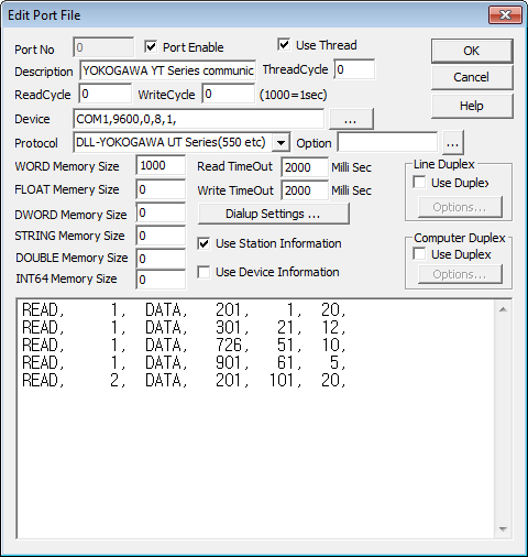
<Figure 1> is read setting example of YOKOGAWA UT Series communication driver.
Note) YOKOGAWA UT Series PID controller basically uses MODBUS protocol.
 |
| <Figure 1> Read setting example of YOKOGAWA UT Series communication driver |
Device part of <Figure 1> input Device type(COM1), Com Baud(9600), Parity Bit(0), Data Bit(8), Stop Bit(1).
Device settings of YOKOGAWA UT Series are changed according to PID controller settings
Com Baud, Parity, Data and Stop Bit of YOKOGAWA UT Series can be changed by operation control of PID controller.
Read schedule example
| Memory | Station | Data Type | Read start address(Modbus Address) | Save start address | Read size |
| READ, | 1, | DATA, | 201, | 1, | 20, |
| READ, | 1, | DATA, | 301, | 21, | 12, |
| READ, | 1, | DATA, | 726, | 51, | 10, |
| READ, | 1, | DATA, | 901, | 61, | 5, |
| READ, | 2, | DATA, | 201, | 101, | 20, |
1) Station : Station number of YOKOGAWA UT Series PID controller. (1 ~ 99)
2) Data Type : Data type to read. Always DATA : Fixed to Function 3 of Modbus protocol.
3) Read start address : Modbus protocol address of YOKOGAWA UT Series. (<Table 1>, <Figure 7> ~ <Figure 11> or refer to UT Series manual)
4) Save start address for Communication Server : Buf position to save the read state value.
5) Read size : Read size. (1 ~ 64)
Save contents and save location of data type are as follows.
| Address | Contents | Description |
| 1 ~ 49 | Data Displayed for Operation | PV, SP, OUT etc (Read only) |
| 50 ~ 100 | User Area | R/W |
| 201 ~ 230 | Operation Mode Parameter | A/M, C/A/M, MOUT etc |
| 231 ~ 300 | Loop 1 ~ 2ÀÇ Operation–related Parameter | AT, SC, BS, FL etc |
| 301 ~ 700 | Loop 1 ~ 2ÀÇ PID Parameter | P, I, D etc |
| 701 ~ 800 | Ten-segment Linearizer Parameters and User Parameters | 1.AI ~ 1.PMD etc |
| 801 ~ 900 | Display Messages (Message Texts) | Display Messages |
| 901 ~ 1000 | Loop 1 ~ 2ÀÇ Control Action Parameters | SP, ALM, CTL |
| 1001 ~ 1100 | Loop-common Function Parameters | AIN, RET, TRND, LOCK |
| 1101 ~ 1200 | Display and I/O Configuration Parameters | CSEL, DO, DI, C.PYS |
| 1201 ~ 1300 | Controller Mode, PV Input, Control Output Parameters | UTMD, IN, OUT, R485, INIT |
| 1301 ~ 1500 | Input Block | Block Input/Output and Module Output |
| 1501 ~ 1700 | Output Block | |
| <Table 1> Contents by address of YOKOGAWA UT Series | ||
If you click the icon
![]() in protocol
option part, you can see the dialog box such as <Figure 2>. you can also set
read schedule by using this part.
in protocol
option part, you can see the dialog box such as <Figure 2>. you can also set
read schedule by using this part.
 |
| <Figure 2> Example of YOKOGAWA UT Series protocol option dialog box |
You can set read schedule by using
![]() ,
,
![]() ,
,
![]() button and
listbox of <Figure 2>.
button and
listbox of <Figure 2>.
 |
| <Figure 3> Example of YOKOGAWA UT Series's read schedule Add/Edit dialog box |
When you click Add button or Edit button in dialog box of <Figure 2>, dialog box of <Figure 3> is shown.
Write to direct address of controller, regardless of SCAN File.
Digital Write
Digital write and analog write have the same setting parameters except output value(0, 1).
Analog Write
Analog write send WORD data value to PID controller.
You can set SP, MOUT value, etc of PID controller by using the analog writing.
Analog write setting parameters are as follows :
1) PORT Connected Port number.
2) STATION Station number of PID controller. (1 ~ 99).
3) Address YOKOGAWA UT Series's Data Address(<Table 1>, <Figure 7> ~ <Figure 11> or refer to UT Series manual). Use decimal address.
4) Extra1 Don't care.
5) Extra2 Don't care.
Communication cable connection between YOKOGAWA UT Series PID controller and computer.
Connect no.23(SDB : T+), no.24(SDA : T-), no.25(RDB : R+), no.26(RDA : R-) terminal of YOKOGAWA UT Series's back side terminal block(Refer to <Figure 4>) with (485 communication terminal) R+, R-, T+, T- of computer side, in order.
YOKOGAWA UT Series side Computer side
No.23 terminal (SDB : T+) ------------------------- R+
No.24 terminal (SDA : T-) ------------------------- R-
No.25 terminal (RDB : R+) ------------------------- T+
No.26 terminal (RDA : R-) ------------------------- T-
 |
| <Figure 4> Back side terminal block of YOKOGAWA UT Series(UT550) |
Basic power connection of YOKOGAWA UT Series) Connect basic power no.9(N)2 with no.8(L) of <Figure 4>. (AC 100 ~ 240V)
 |
| <Figure 5> Side terminal block of YOKOGAWA UT Series(UT550) |
 |
|
<Figure 6> Front side of YOKOGAWA UT Series(UT550) PID controller |
Meter Address, Com Baud settings
You can set Address(1~99) of PID controller, Com Baud, etc by using the front side control button of YOKOGAWA UT Series(Refer to <Figure 6>).
 |
| <Figure 7> Process Data And User Area |
 |
| <Figure 8> Operation Mode and Computation Parameters |
 |
| <Figure 9> Part of Loop1 PID Parameters |
 |
| <Figure 10> Part of User Parameters, Ten-segment Linearizer Parameters, and Messages |
 |
| <Figure 11> Part of Control Action, Loop-common Function, and I/O Configuration Parameters |