Tascon Power Meter communication driver is the driver to communicate with power meter of Tascon Co., Ltd. in Korea.
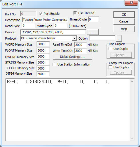
<Figure 1> is read setting example of Tascon Power Meter communication driver.
|
|
| <Figure 1> Read setting example of Tascon Power Meter communication driver |
Device part of <Figure 1> input Device type(TCP/IP), IP address of PLC(192.168.2.200), service port of TCP/IP protocol ( 6000 ),respectively, according to setting of controller.
Tascon Power Meter communication driver read schedule
Read schedule setting parameters are as follows:
1) Station – Tascon controller station number = 0 ~ 999999999999. Max 12 digit, decimal unit.
2) Read command – Command = WATT, CURR. ( Refer to <Table 1> )
3) Read start address – Don't care.
4) Save Start Address for Communication Server – saveing start address of Communication Server.
5) Read Size – Fixed to 1.
Read schedule example)
READ, 11313024000, WATT, 0, 0, 1,
<Table 1> is data saving address and contents of Tascon Power Meter communication driver for each read command.
| Read command | Contents |
Data Saving Address | Range |
| WATT | Read of power | Statr addr + 0 : Power | float, double data |
| CURR | Read of power at communication status | Statr addr + 0 : Power | |
| <Table 1> Data saving address and contents of Tascon Power Meter communication driver for each read command | |||
Tascon Power Meter Genius communication driver store the same data in WORD, DWORD, FLOAT, DOUBLE, INT64 memory, but the data format are different.
If you click the icon ![]() in protocol option part, you
can see the dialog box such as <Figure 2>. you can also set read schedule by
using this part.
in protocol option part, you
can see the dialog box such as <Figure 2>. you can also set read schedule by
using this part.
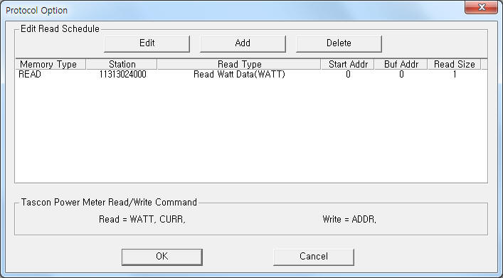 |
| <Figure 2> Example of Tascon Power Meter communication driver’s Option dialog box |
You can set read schedule by using ![]() ,
, ![]() ,
, ![]() button and listbox
of <Figure 2>.
button and listbox
of <Figure 2>.
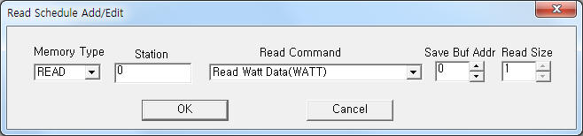 |
| <Figure 3> Example of Tascon Power Meter communication driver’s read schedule Add/Edit dialog box |
When you click Add button or Edit button in dialog box of <Figure 2>, dialog box of <Figure 3> is shown.
You can read controller's station number by using write settings.
Digital Write
Digital write and Analog write have the same setting parameters except output value(0 or 1).
Analog Write
Analog write setting parameters are as follows:
1) PORT Port no. (0 ~ 255)
2) STATION Don't care.
3) ADDRESS Saving address of readed Tascon controller's station number. .( Refer to INT64 memory )
4) Extra1 Write command : ADDR.
5) Extra2 Don't care.
Note) You can read controller's station number by using 'ADDR' write command when only single connection. (can't read when multi-drop connection)
Write example 1)
PORT : 0 STATION : 0 ADDRESS : 0100 EXTRA1 : ADDR EXTRA2 :
The setting parameter shown above is a controller's station number read example when single connection. After write, the readed controller station save at 100 address WORD, DWORD, FLOAT, DOUBLE/, NT64 memory.
<Figure 4> shows the appearance of Tascon Power Meter controller.
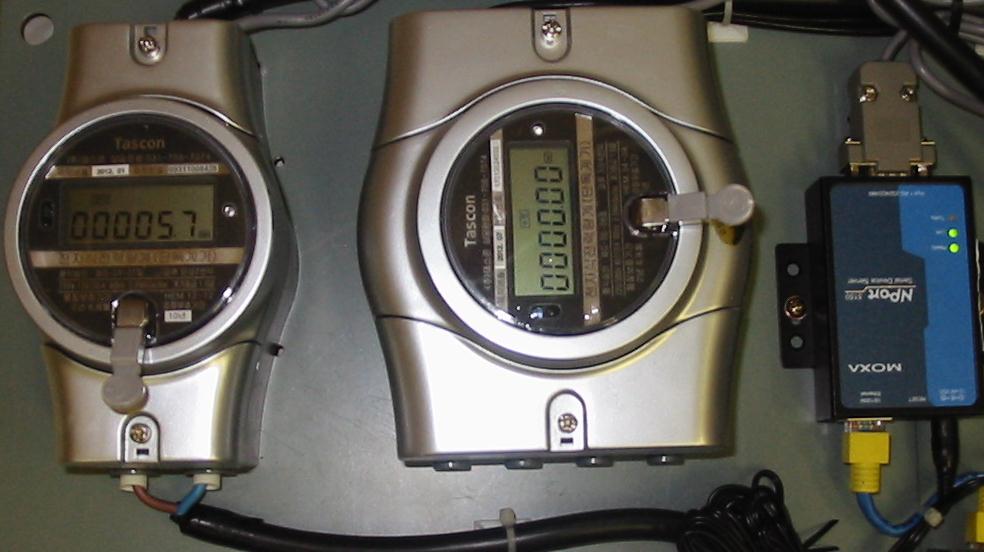 |
| <Figure 4> Appearance of Tascon Power Meter controller |