TCU for Standby Power communication driver is the driver to communicate with standby power monitoring controller of M.Nextec LNC. in Korea.
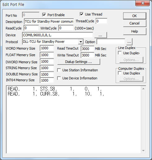
<Figure 1> is read setting example of TCU for Standby Power communication driver.
|
|
| <Figure 1> Read setting example of TCU for Standby Power communication driver |
Device part of <Figure 1> input Com Port(COM8), Baud Rate(9600), Parity Bit(0), Data Bit(8), Stop Bit(1) respectively, according to setting of controller.
TCU for Standby Power communication driver read schedule
Read schedule setting parameters are as follows:
1) TCU ID – 0 ~ 99 TCU ID.
2) Read command – command = STS.xx, CURR.xx, SB.xx. ( refer to <Table 1> )
3) Read device ID – device ID number.
4) Save start address for Communication Server – Saving start address of Communication Server.
5) Read Size – fixed to 1.
Read schedule example)
READ, 1, STS.S8, 1, 0, 1,
READ, 1, CURR.S8, 1, 10, 1,
<Table 1> is read command and contents of TCU for Standby Power.
<Table 2> is data saving address and contents of STS read command. Also, <Table 3> is data saving address and contents of CURR, SB read command.
| Read command | Contents | Remarks |
| STS.xx | read of output status | xx = sort of device, S8, S4, S2, S1, F8, F4, R8, R4 (S = switch, F = FRTU, R = relay) |
| CURR.xx | read of current power of FRCU | |
| SB.xx | read of setting standby power of FRCU | |
| <Table 1> Read command and contents of TCU for Standby Power | ||
| Data saving address | Contents | Remarks |
| start addr + 0 | relay On/Off status | 1 = On, 0 = Off |
| start addr + 1 | Auto/Manual status for each channel | 1 = Auto, 0 = Manual |
| start addr + 2 | Flag Under status | 1 = standby >= current 0 = standby < current |
| <Table 2> Data saving address and contents of STS read command | ||
| Data saving address | Contents | Remarks |
| start addr + 0 ~ 7 | current/standby power value of channel 1 ~ 8 | word unit real value = read value / 10 |
| <Table 3> Data saving address and contents of CURR, SB read command | ||
TCU for Standby Power communication driver store the same data in WORD, DWORD, FLOAT memory, but the data format are different.
If you click the icon ![]() in protocol option part at
<Figure 1>, you
can see the dialogue box such as <Figure 2>. you can also set read schedule by
using this part.
in protocol option part at
<Figure 1>, you
can see the dialogue box such as <Figure 2>. you can also set read schedule by
using this part.
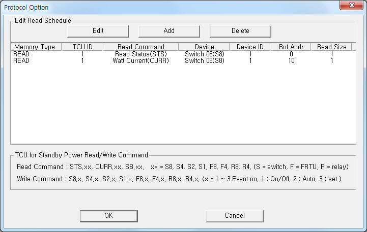 |
| <Figure 2> Example of TCU for Standby Power communication driver’s Option dialog box |
You can set read schedule by using ![]() ,
, ![]() ,
, ![]() button and listbox of <Figure
2>.
button and listbox of <Figure
2>.
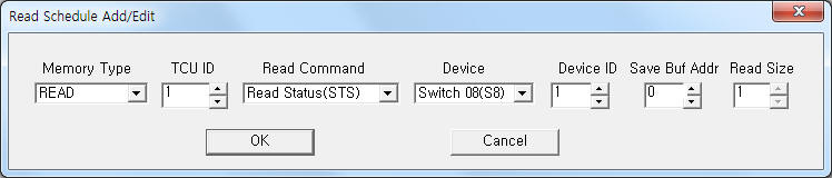 |
| <Figure 3> Example of TCU for Standby Power communication driver’s read schedule Add/Edit dialog box |
When you click Add button or Edit button in dialogue box of <Figure 2>, dialogue box of <Figure 3> is shown.
You can control TCU controller by using 'write settings'.
Digital Write
Digital write and analog write have the same setting parameters except output value.
Analog Write
Analog write setting parameters are as follows:
1) PORT Port no. (0 ~ 255)
2) STATION 0 ~ 99 TCU ID.
3) ADDRESS device ID number.
4) Extra1 writing command = S8.x, S4.x, S2.x, S1.x, F8.x, F4.x, R8.x, R4.x. (S = switch, F = FRTU, R = relay)
x : 1 ~ 3 Event number, 1 = Relay On/Off (RELAY,standby module), 2 = Auto/Manual change(only standby module), 3 = setting of standby power(only standby module)
5) Extra2 channel number.
Write example 1)
PORT:0, station:1, ADDRESS:0002, Extra1: S8.1, Extra2 : 3
The setting parameter shown above is Relay On( 1 )/Off( 0 ) control example of TCU ID = 1, device ID = 2, Switch 8 module, channel number = 3.
Block Write
TCU for Standby Power communication driver don't support 'Block Write'.
Connection of main power and communication cable are as follows:
Connection of main power
Please connect 24V DC main power to +24, 0 connector such as <figure 4>.
Connection of communication cable
Please connect RS-485 communication cable to A2( + ), B2( - ) connector.
<Figure 4> is connection example of main power and communication cable to TCU controller.
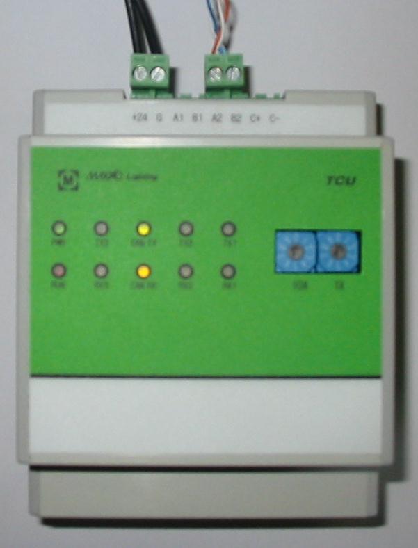 |
| <Figure 4> Connection example of main power and communication cable to TCU controller |