DAIKIN SUT Series communication driver is driver to communicate with Hybrid hydraulic systems of DAIKIN industries, Ltd. in Japan.
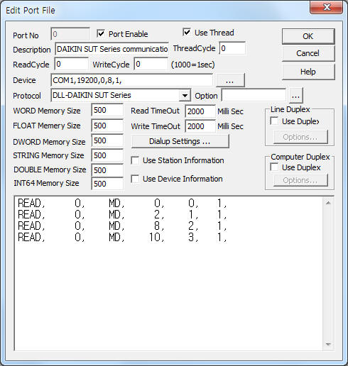
<Figure 1> is read setting example of DAIKIN SUT Series communication driver.
|
|
| <Figure 1> Read setting example of DAIKIN SUT Series communication driver |
Device part of <Figure 1> input Com Port(COM1), Baud Rate(19200), Parity Bit(0), Data Bit(8), Stop Bit(1) respectively, accordint to the setting of system.
Read schedule of DAIKIN SUT Series communication driver
Read schedule setting parameters are as follows:
1) Station – don't care.
2) Read command – fixed to MD.
3) Read start address – reading memory address. ( refer to <Table 1>)
4) Save start address for Communication Server – Saving start address of Communication Server.
5) Read size – fixed to 1.
Read schedule example)
READ, 0, MD, 0, 0, 1,
READ, 0, MD, 2, 1, 1,
READ, 0, MD,
8, 2, 1,
READ, 0, MD, 10, 3, 1,
<Table 1> is memory address and parameter of DAIKIN SUT Series communication driver.
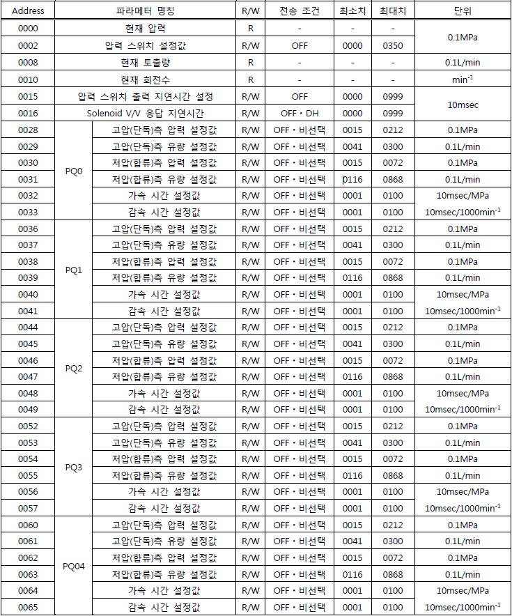 |
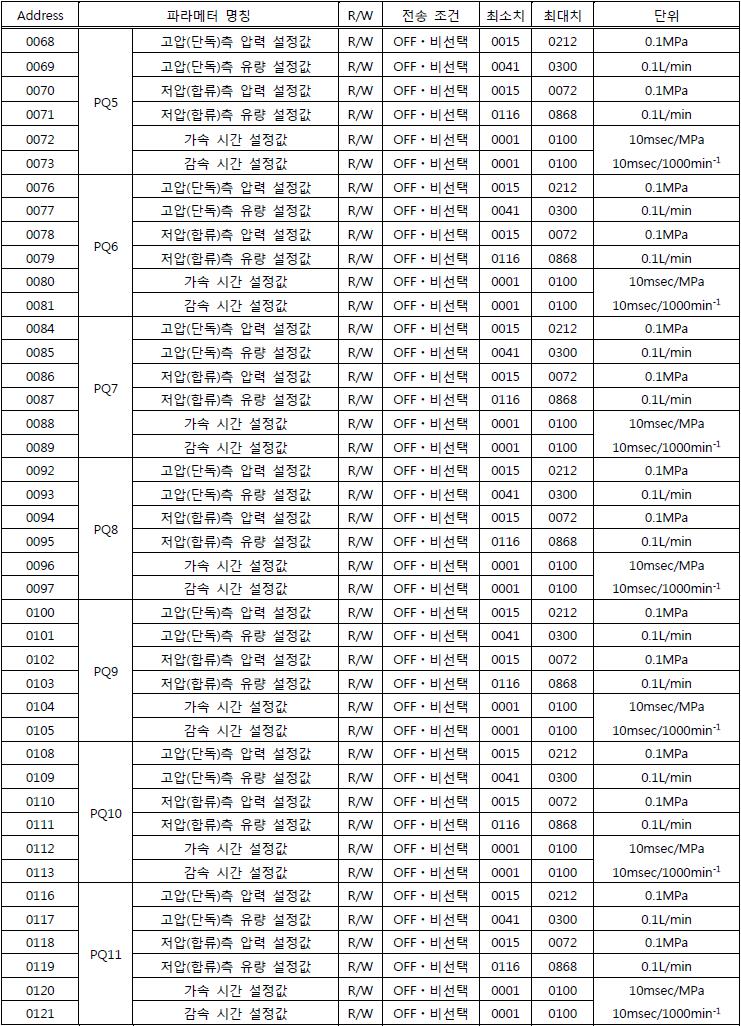 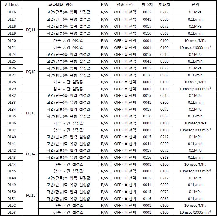 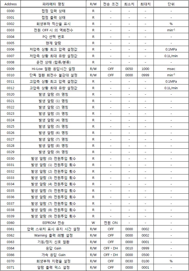 <Table 1> Memory address and parameter of DAIKIN SUT Series communication driver |
DAIKIN SUT Series communication driver store the same data in WORD, DWORD, FLOAT, DOUBLE( also save STRING for alarm command ) memory, but the data format are different.
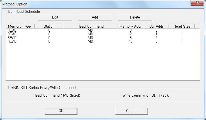
If you click the icon ![]() in protocol option part at
<Figure 1>, you
can see the dialog box such as <Figure 2>. you can also set read schedule by
using this part.
in protocol option part at
<Figure 1>, you
can see the dialog box such as <Figure 2>. you can also set read schedule by
using this part.
 |
|
<Figure 2> Example of DAIKIN SUT Series communication driver’s Option dialog box |
You can set read schedule by using
![]() ,
,
![]() ,
,
![]() button and listbox of <Figure
2>.
button and listbox of <Figure
2>.
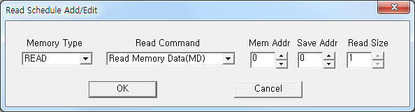 |
| <Figure 3> Example of DAIKIN SUT Series communication driver’s read schedule Add/Edit dialog box |
When you click Add button or Edit button in dialog box of <Figure 2>, dialog box of <Figure 3> is shown.
You can set DAIKIN SUT Series controller by using 'write settings'.
Digital Write
Digital write and analog write have the same setting parameters except output value.
Analog Write
Analog write setting parameters are as follows:
1) PORT Port no. (0 ~ 255)
2) STATION don't care.
3) ADDRESS writing memory address( decimal unit ). ( refer to <Table 1> )
4) Extra1 fixed to SD.
5) Extra2 don't care.
Write example 1)
PORT : 0 STATION : 0 ADDRESS : 0055 EXTRA1 : SD EXTRA2 : 0
The setting parameter shown above is flowrate setting example for lower voltage.
Write example 2)
PORT : 0 STATION : 0 ADDRESS : 0056 EXTRA1 : SD EXTRA2 : 0
The setting parameter shown above is pressurized time setting example.