SPD-110 Display Controller communication driver is the driver to communicate with LED display controller of SPDDATA.
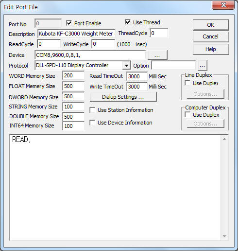
<Figure 1> is read setting example of SPD-110 Display Controller communication driver.
 |
| <Figure 1> Read setting example of SPD-110 Display Controller communication driver |
Device part of <Figure 1> input Device Com port( COM6 ), Baud rate( 19200 ), Parity bit( 0 ), Data bit( 8 ), Stop bit( 1 ) respectively, according to setting of controller.
SPD-110 Display Controller communication driver read schedule
Read schedule setting parameters are as follows:
SPD-110 Display Controller communication driver's read schedule input 'READ' one line.
If you click the icon
![]() in protocol option part, you can see the dialogue
box such as <Figure 2>.
in protocol option part, you can see the dialogue
box such as <Figure 2>.
 |
| <Figure 2> Example of SPD-110 Display Controller communication driver¡¯s Option dialogue box |
You can write emergency text by using write settings.
Digital write
Digital write and analog write have the same setting parameters except output value(0 or 1).
Analog write
Analog write setting parameters are as follows:
1) PORT port no. (0 ~ 255)
2) STATION station number of controller.
3) Address output format and text color data reading start WORD memory address when EMER write command, Extra2 = 255( output format 11 byte + n text color)
4) Extra1 write command = POWER, COLOR, EMER
POWER : power On/Off of SPD-110 controller, ( output value : 1 = On, 0 = Off )
COLOR : color setting for total display screen, ( output value : 0 = clear, 1 = red, 2 = green, 3 = amber )
EMER : emergency message command. ( format : EMER.xxx~ ( xxx~ = string) )
5) Extra2 output color and format when EMER write command : 0, 1, ... = red, 1 = green, 3 = amber, 4 = black, 255 = get output format 11 byte + n text color from 'Address ~' WODR memory (EMER user setting write command, refer to <Table 1>).
<Table 1> is address for output format, text color and contents of EMER user setting command.
| Address for output format, text color | Contents |
| Start address + 0 | module count of 0 ~ Y axle: block position of message |
| Start address + 1 |
B[1:0]
display method( 0 = normal, 1 = clear) B[3:2] Dummy B[7:4] background image |
| Start address + 2 | number of repeat(0 ~ 239, 240 = unlimit) |
| Start address + 3 |
Bit[3:0]
font size Bit[5:4] display( 0 = don't, 1 = display, 2 = overlay) Bit[7:6] direction(0 = 1 line, 1 = vertical, 2 = horizontal) |
| Start address + 4 |
module number for split screen Bit[3:0] - left module number for split screen Bit[7:4] - right module number for split screen |
| Start address + 5 | text color format(0 = add color block, 1 = add separation character) |
| Start address + 6 | split screen effect value |
| Start address + 7 | main screen effect value |
| Start address + 8 | effect speed of normal text(0 ~ 255) |
| Start address + 9 | stop time after normal text effect(500msec unit) |
| Start address + 10 | module count of 0~ Y axle: vertical position |
| Start address + 12 ~ | each text color( input contents of Extra1 ) 0, 1, ... = red, 2 = green, 3 = amber, 4 = black |
| <Table 1> Address for output format, text color and contents of EMER user setting command | |
Write example 1)
PORT:0, station:0, ADDRESS:0000, Extra1:EMER.123.4 56, Extra2 : 1
The setting parameter shown above is emergency message writing example. ( output value = 123.4 56, text color = red )
Write example 2)
PORT:0, station:0, ADDRESS:0000, Extra1:EMER.123.4 56, Extra2 : 2
The setting parameter shown above is emergency message writing example. ( output value = 123.4 56, text color = green )
Write example 3)
PORT:0, station:0, ADDRESS:0000, Extra1:EMER.123.4 56, Extra2 : 255
The setting parameter shown above is emergency message writing example. ( output value = 123.4 56, text format and color = read from 0 ~ 10, 11 ~ 18 WORD memory )
<Figure 3> is appearance of SPD-110 Display Controller.
 |
| <Figure 3> Appearance of SPD-110 Display Controller |