SABROE Protocol 0178-400 Communication Driver is the driver to communicate with Comressor/Chiller of Sabroe Refrigeration in Denmark.
Note) SABROE Protocol 0178-400 Communication Driver's help is written by Comressor equipment.
You can reference to SABROE Protocol 0178-400 manual for Chiller equipment's point address, ... etc.
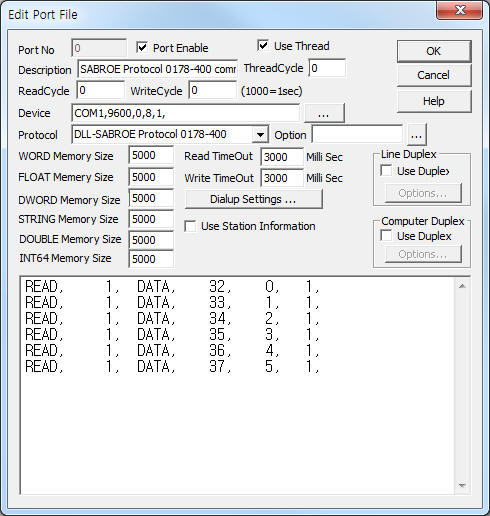
<Figure 1> is read setting example of SABROE Protocol 0178-400 communication driver.
|
|
| <Figure 1> Read setting example of SABROE Protocol 0178-400 communication driver |
Device part of <Figure 1> input Com Port(COM1), Baud Rate(9600), Parity Bit(0), Data Bit(8), Stop Bit(1) respectively.
SABROE Protocol 0178-400 communication driver’s read schedule
Read schedule setting parameters are as follows:
1) STATION – 0 ~ 14 equipment address.
2) Equipment type – DATA or COP.
3) Read Start Address – point no. = 32 ~ 255. (Refer to <Table 1>, <Table 2>)
4) Save Start Address for Communication Server – Saving start address of Communication Server.
5) Read Size – Size = Fix to 1.
Read schedule example)
READ, 1, DATA, 32, 0, 1,
READ, 1, DATA, 33, 1, 1,
READ, 1, DATA, 34, 2, 1,
READ, 1, DATA, 35, 3, 1,
READ, 1, DATA, 36, 4, 1,
READ, 1, DATA, 37, 5, 1,
<Table 1> is a description of 'DATA' read command's point no. and stored values of SABROE Protocol 0178-400 communication driver.
<Table 2> is a description of 'COP' read command's point no. and stored values of SABROE Protocol 0178-400 communication driver.
| point no. | Stored Values(Start Add + 0) | Real data | Unit or Range | Remarks |
| 32 | Suction gas temperature | Read value / 10.0 | °C | Real data = -99.9 ~ 9999.9 |
| 33 | Disch. gas temperature | |||
| 34 | Oil temperature | |||
| 35, 36 |
Suct. pressure, Disch. pressure |
BAR | ||
| 37, 38 |
Suct. pressure, Disch. pressure |
°C/R | ||
| 39 | Capacity position | % | ||
| 40 | Volume slide position | % | ||
| 41 | Motor current | Amps | ||
| 42 | Universal regulator | % | ||
| 43 | Oil filter diff.pressure (s) / intermediate pressure (r) |
BAR | ||
| 44, 45 |
Suct. gas superheat/ Brine /intermediate temperature |
°C | ||
| 46 | Running hours | Read value | Hours | 0 ~ 65535 |
| 47, 48, 49 |
Setp.1, suct.press, Setp.2, suct.press, N.zone, suct.press |
Read value / 10.0 | °C/R | |
| 50 | Set point actual, brine temp | |||
| 51 | N.zone, brine temp | |||
| 52 ~ 56 | Alarm 1 ~ 6 | Read value | status value(bit) | |
| 57 ~ 61 | Warning 1 ~ 6 | |||
| 62 | Compressor mode | |||
| 63 | Control mode | |||
| 64 | Startsequence no. | |||
| 65 ~ 78 | Suct.system 1 ~ 14 regulator | |||
| 79 | System for this unit | |||
| 80 | Which control system | |||
| 81 | Oil pressure | Read value / 10.0 | BAR | Real data = -99.9 ~ 9999.9 |
| 82 | MultiSab state | Read value | ||
| 83 | Preceding compr | 1~14 | ||
| 84 | Next compr. | |||
| 85 | Cmp to follow the next | |||
| 86 | Selected sysregulator | |||
| 87 | Communication errors | % | ||
| 88 | Not used | |||
| 89 | Disch.gas superheat | Read value / 10.0 | °C | Real data = -99.9 ~ 9999.9 |
| 90 | Switch reg. SP1/SP2 | Read value | 0~1 | |
| 91 | Set point actual, suct. press. | Read value/ 10.0 | °C/R | Real data = -99.9 ~ 9999.9 |
| 92 | P.band, suct. press. | |||
| 93 | Set point 1, brine temp. | °C | ||
| 94 | Set point 2, brine temp. | |||
| 95 | P. band, brine temp. | |||
| 06 | Set point actual, discharge | °C/R | ||
| 97 | Set point 1, discharge | |||
| 98 | Set point 2, discharge | |||
| 99 | N. zone, discharge | |||
| 100 | P. band, discharge | |||
| 101 | Set point actual, external | % | ||
| 102 | Set point 1, external | |||
| 103 | Set point 2, external | |||
| 104 | N. zone, external | |||
| 105 | P. band, external | |||
| 106 | Set point 1, oil pressure | BAR | ||
| 107 | Set point 2, oil pressure | |||
| 108 | Switch motor SP1/SP2 | Read value | 0~1 | |
| 109 | Set point 1, motor curr. | Amps | ||
| 110 | Set point 2, motor curr. | |||
| 111 | Ext. starting permission - normal | 0~1 | ||
| 112 | Ext. starting permission - instant | |||
| 113 | Start request OK (PMS) | |||
| 114 | Set point 1, oil temp. -- cooling | Read value / 10.0 | °C | Real data = -99.9 ~ 9999.9 |
| 115 | Set point 2, oil temp. -- heating | |||
| 116 | N. zone, oil temp. | |||
| 117 | P. band, oil temp. | |||
| 118 | Set point 1, suct. gas superheat | |||
| 119 | Set point 1, disch. gas temp. | |||
| 120 | Set point 1, volume slide | % | ||
| 121 | Run time since last start | Read value | Sek | |
| 122 | Setpoint 1, capacity | Read value / 10.0 | % | Real data = -99.9 ~ 9999.9 |
| 123 | N. zone capacity | |||
| 124 | P. band capacity | |||
| 125 | Cap. mode | Read value | 0~1 | |
| 127 | Software version | |||
| 130 | Start-start delay | Sek | ||
| 131 | Stop-start delay | |||
| 132 | Delay before start | |||
| 133 | Delay before stop | |||
| 134 | Suct. press. ramp function | |||
| 135 | Slide max. down time (s)/ Delay up (r) |
|||
| 136 | Prelubrication (s)/ Delay down (r) |
|||
| 137 | Oil flow switch active (s)/ Take over max. time (r) |
|||
| 138 | Oil flow switch delay (s)/ Take over delay (r) |
|||
| 139 | Oil flow max. drop out (s)/ M-press. (r) |
|||
| 140 | Lubrication time after start (s)/ not used (r) |
|||
| 141 | Difference pressure OK (s)/ not used (r) |
|||
| 142 | Oil pressure low -- delay | |||
| 143 | Oil filter diff. press. high (s)/ oil pressure high (r) |
|||
| 144 | Oil temperature low | |||
| 145 | Oil temperature high | |||
| 146 | Superheat low | |||
| 147 | Superheat high | |||
| 148 | Discharge press. overload | |||
| 149 | Motor current overload | |||
| 150 | Compr. motor starting time | |||
| 151 | PMS feed back | |||
| 152 | Full flow pump starting time (s)/ not used (r) |
|||
| 153 | Oil pump starting time (s)/ not used (r) |
|||
| 154 | Oil rectifier start | |||
| 155 | Oil rectifier delay | |||
| 156 | Oil rectifier suppress | |||
| 157 | Start High press. | |||
| 158 | Communication delay | |||
| 159 | Cap. negative | |||
| 160 | P.band factor, start delay | 1~10 | ||
| 161 | P.band factor, stop delay | |||
| 162 | P.band factor, delay up (r) | |||
| 163 | P.band factor, delay down (r) | |||
| 164 | Transfer factor, delay down (r) | |||
| 165 | Transfer zone, delay down (r) | % | ||
| 166 | Take over factor, delay up (r) | 1~10 | ||
| 167 | Take over factor, start delay (r) | |||
| 168 | Take over zone, delay up (r) | % | ||
| 170 | Compressor type | 1~50 | ||
| 171 | Refrigerant type | 1~9 | ||
| 172 | Regulation mode | 0~5 | ||
| 173 | VI-control mode | 0~1 | ||
| 174 | Automatic start | |||
| 175 | Automatic stop | |||
| 176 | Prelubrication | |||
| 177 | Full flow pump | |||
| 178 | Booster | |||
| 179 | Compressor no. | 0~14 | ||
| 180 | Regulation master choice | 0~1 | ||
| 181 | Economizer | |||
| 182 | Economizer min. capacity | Read value / 10.0 | % | Real data = -99.9 ~ 9999.9 |
| 183 | Economizer max. suct. press. | °C/R | ||
| 184 | Common condenser | Read value | 0~3 | |
| 185 | HP compr. on two stage | 0~1 | ||
| 186 | Discharge cooling | |||
| 187 | Oil cooling type | 0~4 | ||
| 188 | Motor current range | Amps | ||
| 189 | Swept volume | m3/h | ||
| 190 | Cold store control | 0~1 | ||
| 191 | Out door temp. compensation | |||
| 192 | Total unload | |||
| 193 | Baud rate | baud | ||
| 194 | Oil rectifier | 0~1 | ||
| 195 | Eur./US-units | |||
| 196 | Factory reset | |||
| 197 | Language | 1-15 | ||
| 198 | Contrast | % | ||
| 199 | Aux. analog input function | 0-6 | ||
| 200 | Aux. digital output function | 0-5 | ||
| 201 | Cap. lim. low | Read value / 10.0 | % | Real data = -99.9 ~ 9999.9 |
| 202 | Cap. lim. high | |||
| 203 | Manual zero | |||
| 204, 205, 206, 207 | Suct. pressure limits -- high alarm, high warning, low warning, low alarm | BAR | ||
| 208, 209, 210, 211 | Disch.pressure limits -- high alarm, high warning, low warning, low alarm | |||
| 212, 213, 214, 215 | Oil pressure limits -- high alarm, high warning, low warning, low alarm | |||
| 216, 217, 218, 219 | Oil filter diff. press. limits (s) / Interm.press.limits(r) -- high alarm, high warning, low warning, low alarm |
|||
| 224, 225, 226, 227 | Disch.temp. limits -- high alarm, high warning, low warning, low alarm | °C | ||
| 228, 229, 230, 231 | Oil temp. limits --high alarm, high warning, low warning, low alarm | |||
| 232, 233, 234, 235 | Brine temperature (a) limits / intermediate temp. (b) limits -- high alarm, high warning, low warning, low alarm |
|||
| 236, 237, 238, 239 | Suct.gas superheat -- high alarm, high warning, low warning, low alarm | |||
| 240, 241, 242, 243 | Disch.gas superheat -- high alarm, high warning, low warning, low alarm | |||
| 244, 245, 246, 247 | External input limits -- high alarm, high warning, low warning, low alarm | % | ||
| 248, 249, 250, 251 | Suct. pressure limits -- high alarm, high warning, low warning, low alarm | °C/R | ||
| 252, 253, 254, 255 | Disch.pressure limits -- high alarm, high warning, low warning, low alarm | |||
| <Table 1> 'DATA' read command's point no. and stored values of SABROE Protocol 0178-400 communication driver | ||||
| point no. | Stored Values(Start Add + 0) | Real data | Unit or Range | Remarks |
| 32 | COP | Read value / 10.0 | Real data = -99.9 ~ 9999.9 |
|
| 33 | COP Carnot | |||
| 34 | COP Mechanical | |||
| 35 | Cooling Power | Read value | Kw | |
| 36 | Mass Flow | kg/h | ||
| 37 | Shaft Power | Kw | ||
| 38 | Motor COP | Read value / 10.0 | Real data = -99.9 ~ 9999.9 |
|
| 39 | Volume Flow | Read value | m3/h | |
| 40 | Superheated Spec. Volume | Read value / 10.0 | l/kg | |
| 41 | Saturated Spec. Volume | |||
| 42 | Enthalpy H1 | Read value | kJ/kg | |
| 43 | Enthalpy H4 | |||
| 44 | Enthalpy H2 | |||
| <Table 2> 'COP' read command's point no. and stored values of SABROE Protocol 0178-400 communication driver | ||||
SABROE Protocol 0178-400 communication driver store the same data in WORD, DWORD, FLOAT memory, but the data formats are different.
If you click the icon
![]() in protocol option part, you can see the dialogue
box such as <Figure 2>. you can also set read schedule by using this part.
in protocol option part, you can see the dialogue
box such as <Figure 2>. you can also set read schedule by using this part.
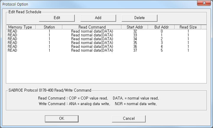 |
| <Figure 2> Example of SABROE Protocol 0178-400 communication driver’s read schedule Add/Edit dialogue box |
You can also set read schedule by using
![]() ,
,
![]() ,
,
![]() button and listbox of <Figure 2>.
button and listbox of <Figure 2>.
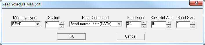 |
| <Figure 3> Example of SABROE Protocol 0178-400 communication driver’s read schedule Add/Edit dialogue box |
When you click Add button or Edit button in dialogue box of <Figure 2>, dialogue box of <Figure 3> will be shown.
You can write setting values of Comressor/Chiller equipment by using write commands.
Bit write
Bit write and word write have the same setting parameters except output value(0 or 1).
Word write
Word write setting parameters are as follows:
1) PORT : Port no. (0 ~ 255)
2) STATION : 0 ~ 14 equipment address.
3) ADDRESS : point no. 32 ~ 255. (Refer to <Table 3>)
4) EXTRA 1 : ANA = analog write point, NOR = normal write point.
5) EXTRA 2 : Don't care.
<Table 3> is a description of point no. and contents, EXTRA1, range for write of SABROE Protocol 0178-400 communication driver.
| Point no(write) | Contents | Extra1 | Write range |
| 32 | Start sequence no. | NOR | 0~14 |
| 33 ~ 46 | Suct.system 1 ~ 14 regulator | 1~14 | |
| 47, 48 | Setp.1 ~ 2, suct.press. | ANA | Write range = Real data x 10.0 |
| 49 | N.zone, suct.press | ||
| 50 | Setpoint 1, brine temp | ||
| 51 | N.zone, brine temp | ||
| 52 | Setpoint for capacity | ||
| 53 | Start compressor | NOR | 1 |
| 54 | Stop compressor | 0 | |
| 55 | Select suction system | 1~14 | |
| 56 | Setpoint 2, brine temp | ANA | Write range = Real data x 10.0 |
| 63 | Control mode | NOR | 0~3 |
| 92 | P.band, suct. press. | ANA | Write range = Real data x 10.0 |
| 95 | P. band, brine temp. | ||
| 97 | Set point 1, discharge | ||
| 98 | Set point 2, discharge | ||
| 99 | N. zone, discharge | ||
| 100 | P. band, discharge | ||
| 101 | |||
| 102 | Set point 1, external | ANA | Write range = Real data x 10.0 |
| 103 | Set point 2, external | ||
| 104 | N. zone, external | ||
| 105 | P. band, external | ||
| 106 | Set point 1, oil pressure | ||
| 107 | Set point 2, oil pressure | ||
| 109 | Set point 1, motor curr. | NOR | |
| 110 | Set point 2, motor curr. | ||
| 114 | Set point 1, oil temp. -- cooling | ANA | Write range = Real data x 10.0 |
| 115 | Set point 2, oil temp. -- heating | ||
| 116 | N. zone, oil temp. | ||
| 117 | P. band, oil temp. | ||
| 118 | Set point 1, suct. gas superh. | ||
| 119 | Set point 1, disch. gas temp. | ||
| 123 | N. zone, capacity | ||
| 124 | P. band, capacity | ||
| 130 | Start-start delay | NOR | |
| 131 | Stop-start delay | ||
| 132 | Delay before start | ||
| 133 | Delay before stop | ||
| 134 | Suct. press. ramp function | ||
| 135 | Slide max. down time (s)/ Delay up (r) | ||
| 136 | Prelubrication (s)/ Delay down (r) | ||
| 151 | PMS feed back | ||
| 154 | Oil rectifier start | ||
| 155 | Oil rectifier delay | ||
| 156 | Oil rectifier suppress | ||
| 157 | Start High press. | ||
| 160 | P.band factor, start delay | 1~10 | |
| 161 | P.band factor, stop delay | ||
| 162 | P.band factor, delay up (r) | ||
| 163 | P.band factor, delay down (r) | ||
| 164 | Transfer factor, delay down (r) | ||
| 165 | Transfer zone, delay down (r) | % | |
| 166 | Take over factor, delay up (r) | 1~10 | |
| 167 | Take over factor, start delay (r) | ||
| 168 | Take over zone, delay up (r) | % | |
| 172 | Regulation mode | 0~5 | |
| 174 | Automatic start | 0~1 | |
| 175 | Automatic stop | ||
| 180 | Regulation master choice | ||
| 181 | Economizer | ||
| 182 | Economizer min. capacity | ANA | Write range = Real data x 10.0 |
| 183 | Economizer max. suct. press. | ||
| 190 | Cold store control | NOR | 0~1 |
| 204, 205, 206, 207 | Suct. pressure limits -- high alarm, high warning, low warning, low alarm | ANA | Write range = Real data x 10.0 |
| 208, 209, 210, 211 | Disch.pressure limits -- high alarm, high warning, low warning, low alarm | ||
| 212, 213, 214, 215 | Oil pressure limits -- high alarm, high warning, low warning, low alarm | ||
| 216, 217, 218, 219 | Oil filter diff. press. limits (s) / Interm.press.limits(r) -- high alarm, high warning, low warning, low alarm |
||
| 224, 225, 226, 227 | Disch.temp. limits -- high alarm, high warning, low warning, low alarm | ||
| 228, 229, 230, 231 | Oil temp. limits --high alarm, high warning, low warning, low alarm | ||
| 232, 233, 234, 235 | Brine temperature (a) limits / intermediate temp. (b) limits -- high alarm, high warning, low warning, low alarm |
||
| 236, 237, 238, 239 | Suct.gas superheat -- high alarm, high warning, low warning, low alarm | ||
| 240, 241, 242, 243 | Disch.gas superheat -- high alarm, high warning, low warning, low alarm | ||
| 244, 245, 246, 247 | External input limits -- high alarm, high warning, low warning, low alarm | ||
| 248, 249, 250, 251 | Suct. pressure limits -- high alarm, high warning, low warning, low alarm | ||
| 252, 253, 254, 255 | Disch.pressure limits -- high alarm, high warning, low warning, low alarm | ||
| <Table 3> Point no. and contents, EXTRA1, range for write of SABROE Protocol 0178-400 communication driver | |||
Write example 1)
PORT:0, station:1, ADDRESS:0032, Extra1:NOR, Extra : 0
The setting parameter shown above is an example of word write for Start sequence no.(0 ~ 14) of SABROE Protocol 0178-400 connected with 0 port and 1 equipment address(station).
Write example 2)
PORT:0, station:1, ADDRESS:0050, Extra1:ANA, Extra : 0
The setting parameter shown above is an example of word write for Setpoint 1, brine temperature of SABROE Protocol 0178-400 connected with 0 port and 1 equipment address(station).
(EXTRA1 : Write range = Real data x 10.0, ex) write value = 275, then, Real data = 27.5)
Block write
SABROE Protocol 0178-400 communication driver don’t support ‘Block write’.