Read Multi ASCII Data communication driver is the driver to communicate with normal controlloer for read ASCII data.
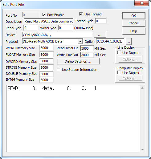
<Figure 1> is read setting example of Read Multi ASCII Data communication driver.
 |
| <Figure 1> Read setting example of Read Multi ASCII Data communication driver |
Device part of <Figure 1> input Com Port(COM1), Baud Rate(9600), Parity Bit(0), Data Bit(8), Stop Bit(1) respectively, according to setting of controller.
In protocol option part, you can set the following: readed data start position at read packet(0 ~ 100, default = 0), end code of read request and receive packet(0 ~ 255, default = 13(CR)), separate code for multi read data(0 ~ 255, default = , (comma)), whether to use read request packet(0 : don't use, 1 : use, default = 1), whether to omit the end code when write request(0 : don't omit, 1 : omit, default = 0), use of check start code(0 : don't check, 1 : check, default = 0), packet start code(0 ~ 255, default = 2), weather to use decimal point is comma data for Float data(0 : default decimal point, 1 : comma, default = 0), weather to use Readed Tatal packet Size(0 : don't use, 1 : use, defalut = 0), packet size when use 'Readed Tatal packet Size'(3 ~ 1024). Each argument is a comma-delimited( , ).
Note) If you have set 'don't use read request packet', the readed data save at the setting 'Address' when writing. (when don't write command, the readed data save 0 ~ WORD, DWORD, FLOAT, STRING memory)
Read Multi ASCII Data communication driver read schedule
Read schedule setting parameters are as follows:
1) Station – Don't care.
2) Read Command – Command = DATA or ASCII character.
3) Read Start Address – Don't care.
4) Save start address for Communication Server – Saving start address of Communication Server.
5) Read Size – Fixed to 1. ( when readed multi ASCII data according separate character, read size = number of readed data, readed data = hxxxx : hex-decimal unit )
6) Weather to use 'user defined read request packet' and read request packet number - 0 = don't use,
1 ~ 255 : read user defined read request code at 'work folder\SCAN\SEND_CODE%03d.ini' file (%03d = user defined read request number). ( refer to <Table 1>).
Note) User defined read request code read only once at communication driver starting.(Writing data read every write command)
Read schedule example)
READ, 0, data, 0, 0, 1, 0,
If you click the icon ![]() in protocol option part, you
can see the dialogue box such as <Figure 2>. you can also set readed data start
position at read packet, end code of read request and receive packet, separate
code for multi read data, whether to use read request packet, whether to omit
the end code when write request, use of check start code, packet start code.
in protocol option part, you
can see the dialogue box such as <Figure 2>. you can also set readed data start
position at read packet, end code of read request and receive packet, separate
code for multi read data, whether to use read request packet, whether to omit
the end code when write request, use of check start code, packet start code.
 |
| <Figure 2> Example of Read Multi ASCII Data communication driverí»s Option dialog box |
<Table 1> is making method of ini file for read request code and <Figure 3> is example of making ini file.
filename |
making method of ini file |
work folder\SCAN\SEND_CODE%03d.ini (%03d = 001 ~ 255 read user defined read request code number) |
1) input request code by text at 1st line. 2) separate by comma( , ) fo reach element. 3) number of max read request code = 300. 4) input 0 ~ 255 value( ASCII code ) by decimal unit. ini data example) 02, 65, 66, 03, |
| <Table 1> Making method of ini file for read request code | |
 |
| <Figure 3> Example of making ini file |
You can send specific control code by using write settings.
Digital Write
Digital write and analog write have the same setting parameters except output value.
Analog Write
Analog write setting parameters are as follows:
1) PORT Port no. (0 ~ 255)
2) STATION Don't care.
3) ADDRESS Data saving address of readed data for normal command,
4) Extra1 Write command = _WRITE, etc.
_WRITE : work folder\SCAN\WRITE_DATA%03d.ini(%03d = 1 ~ 255 number of Extra2), write readed Ascii code, the 1st line input data. ( don't check receive packet code )
etc : input writing ASCII character. ( If you set 'don't omit the end code when write request', the packet will be added 'end code' at the end of write packet )
However, when you using user defined writing, Extra1 = don't care.
5) Extra2 Weather to use 'user defined write packet' and write request packet number.
0 : don't care,
1 ~ 255 : _WRITE command = setting of file number, file number : work folder\SCAN\WRITE_DATA%03d.ini(%03d = 1 ~ 255 number of Extra2) ,
etc command = write request packet number when using 'user defined write packet', file number : work folder\SCAN\SEND_CODE%03d.ini (%03d = write request packet numbe).(refer to <Table 1>)
(read the file data before every writing command)
Write example 1)
PORT:0, station:0, ADDRESS:0000, Extra1:set, Extra2 : 0
The setting parameter shown above is 'set' character writing example.
Write example 2)
PORT:0, station:0, ADDRESS:0000, Extra1:_WRITE, Extra2 : 1
The setting parameter shown above is a characters writing example for the readed data of 1st line data 'work folder\SCAN\WRITE_DATA001.ini' file. (after writing, don't check response packet)