X8 PLC Xnet Protocol is the driver to communicate with X8 Series PLC of RS Automation in Korea.
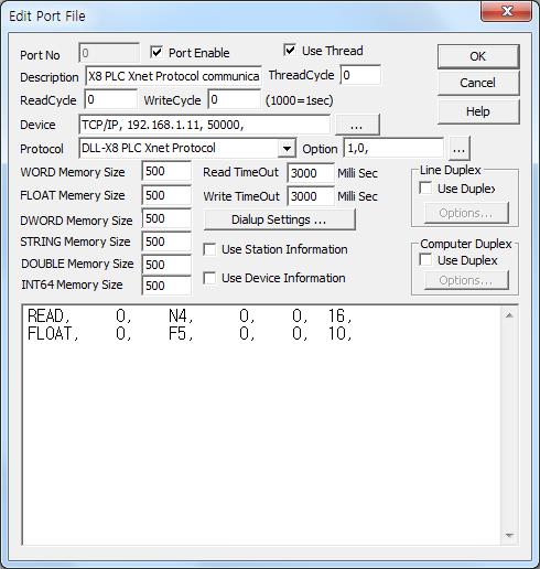
<Figure 1> is read setting example of X8 PLC Xnet Protocol communication driver.
|
|
| <Figure 1> Read setting example of X8 PLC Xnet Protocol communication driver |
Device part of <Figure 1> input device type(TCP/IP), ip address of PLC(192.168.1.11), service port number of TCP/IP(50000), accordint to the setting of controller.
Also, you can set whether to use of Ethernet module( 0 : don't use(serial), 1 : use, default = 1), node number of computer(0 ~ 249, default = 0) by using option part (separated by commas each parameter).
Read schedule of X8 PLC Xnet Protocol communication driver
Read schedule setting parameters are as follows:
1) Station – 0 ~ 249 node number when using serial module. ( Ethernet module : fixed to 254 )
2) Read command – X, Y, SR, B, N, F, L, A, ST, TM, CT, CR Data Table type and 3 ~ 1535( X, Y, SR : don't use) Table number. ( refer to <Table 1> )
3) Read start address – 0 ~ 1535 Table Element number. ( X, Y = 0 ~ 96, ST = 0 ~ 779)
4) Save start address for Communication Server – Saving start address of Communication Server.
5) Read size – read size by Table type ( word, double word, float, string, etc unit )
X, Y, SR, B, N, A = 1 ~ 111,
F, L = 1 ~ 55,
ST = 1 ~ 2,
TM, CT, CR = 1 ~ 22.
6) Extra2 – Sub-Element address when X, Y, F, L, ST, TM, CT CR Table type.
Read schedule example)
READ, 0, N4, 0, 0, 16,
FLOAT, 0, F5, 0, 0, 10,
<Table 1> is Table name/number and Element address of X8 PLC Xnet PLC.
Read command |
Contents |
Element address | Sub-Element address | Words of per Element | Remarsk |
|
| Table name | Table number | |||||
X |
0 (fixed) | Inputs(slot) |
0 ~ 96 | 0 ~ 511 (word offset) | 1 | You can set Table number, Element size at PLC Ladder program |
Y |
1 (fixed) | Outputs(slot) |
0 ~ 96 | 0 ~ 511 (word offset) | 1 | |
SR |
2 (fixed) | System Register |
0 ~ 127 | 0 (fixed) | 1 | |
B |
3 ~ 1535 | Binary |
0 ~ 1535 | 0 (fixed) | 1 | |
N |
3 ~ 1535 | Integer |
0 ~ 1535 | 0 (fixed) | 1 | |
F |
3 ~ 1535 | Floating Point |
0 ~ 1535 | 0 ~ 1 | 2 | |
L |
3 ~ 1535 | Long |
0 ~ 1535 | 0 ~ 1 | 2 | |
A |
3 ~ 1535 | ASCII |
0 ~ 1535 | 0 (fixed) | 1 | |
ST |
3 ~ 1535 | String |
0 ~ 779 | 0 ~ 41 | 42 | |
TM |
3 ~ 1535 | Timer |
0 ~ 1535 | 0 ~ 4 | 5 | |
CT |
3 ~ 1535 | Counter |
0 ~ 1535 | 0 ~ 4 | 5 | |
CR |
3 ~ 1535 | Control |
0 ~ 1535 | 0 ~ 4 | 5 | |
| <Table 1> Table name/number and Element address of X8 PLC Xnet PLC | ||||||
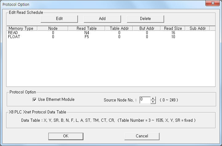
If you click the icon ![]() in protocol option part at
<Figure 1>, you
can see the dialog box such as <Figure 2>. you can also set read schedule by
using this part.
in protocol option part at
<Figure 1>, you
can see the dialog box such as <Figure 2>. you can also set read schedule by
using this part.
 |
|
<Figure 2> Example of X8 PLC Xnet Protocol communication driver’s Option dialog box |
You can set read schedule by using
![]() ,
,
![]() ,
,
![]() button and listbox of <Figure
2>.
button and listbox of <Figure
2>.
Whether to use of Ethernet module and node number of computer can set by using of Protocol Option part in <Figure 2>.
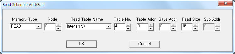 |
| <Figure 3> Example of X8 PLC Xnet Protocol communication driver’s read schedule Add/Edit dialog box |
When you click Add button or Edit button in dialogue box of <Figure 2>, dialogue box of <Figure 3> is shown.
You can set X8 PLC by using 'write settings'.
Digital Write
Digital write setting parameters are as follows:
1) PORT Port no. (0 ~ 255)
2) STATION 0 ~ 249 node number when using serial module. ( Ethernet module : fixed to 254 )
3) ADDRESS writing Element address.
lower 1 digit : 0 ~ F bit position,
higher 3 ~ 7 digit : 0 ~ 1535 Table Element number. ( X, Y = 0 ~ 96, ST = 0 ~ 779)
4) Extra1 write command = X, Y, SR, B, N, F, L, A, ST, TM, CT, CR Data Table type and 3 ~ 1535( X, Y, SR : don't use) Table number. ( refer to <Table 1> )
when the table type is ST, write command format = ST??.xxx. ?? = Table number, xxx = string to be written.
5) Extra2 Sub-Element address when X, Y, F, L, ST, TM, CT CR Table type.
Write example 1)
PORT : 0 STATION : 0 ADDRESS : 005F EXTRA1 : B3 EXTRA2 : 0
The setting parameter shown above is B3 Table, 5 Element number, F bit control(On/Off) example of X8 PLC.
Write example 2)
PORT : 0 STATION : 0 ADDRESS : 0127 EXTRA1 : B3 EXTRA2 : 0
The setting parameter shown above is B3 Table, 12 Element number, 7 bit control(On/Off) example of X8 PLC.
Analog Write
Analog write setting parameters are as follows:
1) PORT Port no. (0 ~ 255)
2) STATION 0 ~ 249 node number when using serial module. ( Ethernet module : fixed to 254 )
3) ADDRESS 0 ~ 1535 Table Element number. ( X, Y = 0 ~ 96, ST = 0 ~ 779)
4) Extra1 write command = X, Y, SR, B, N, F, L, A, ST, TM, CT, CR Data Table type and 3 ~ 1535( X, Y, SR : don't use) Table number. ( refer to <Table 1> )
when the table type is ST, write command format = ST??.xxx. ?? = Table number, xxx = string to be written.
5) Extra2 Sub-Element address when X, Y, F, L, ST, TM, CT CR Table type.
Write example 1)
PORT : 0 STATION : 0 ADDRESS : 0016 EXTRA1 : N4 EXTRA2 : 0
The setting parameter shown above is N4 Table, 16 Element number WORD unit setting example of X8 PLC.
Write example 2)
PORT : 0 STATION : 0 ADDRESS : 0008 EXTRA1 : F5 EXTRA2 : 0
The setting parameter shown above is F5 Table, 8 Element number Float unit setting example of X8 PLC.
Block Write
Block write use PlcScanWriteBlock script such as follows.
script function and parameters : @PlcScanWriteBlock(int port, int station, int address, string extra1, string extra2, object array_value, int array_size);
Block write script example 1 ( N4 Block Write )
ushort Val[10];
Val[0] = 25;
Val[1] = 55;
Val[2] = 31;
Val[3] = 2347;
Val[4] = 3869;
Val[5] = 5;
Val[6] = 72;
Val[7] = 32756;
Val[8] = 541;
Val[9] = 8845;
@PlcScanWriteBlock(0, 0, 0, "N4", 0,
Val, 10);
Block write script example 1 ( F5 Block Write )
float Val[10];
Val[0] = 12286.2;
Val[1] = 255.5;
Val[2] = 32.45;
Val[3]
= 400.567;
Val[4] = 65.12;
Val[5] = 1026.9;
Val[6] = 327.1;
Val[7] =
3.5;
Val[8] = 4.9;
Val[9] = 91.56;
@PlcScanWriteBlock(0, 0, 0, "F5", 0, Val,
10);
Block write script example 1 ( ST8 Block Write )
string str;
@sprintf(str,"abcdefghijklmnopqrstuvwxyz0123456789ABCDEFGHIJKLMNOPQRSTUVWXYZ0123456789");
@PlcScanWriteBlock(0, 0, 0, "ST8", 0, str, 72);
<Figure 4> shows the appearance of X8 PLC.
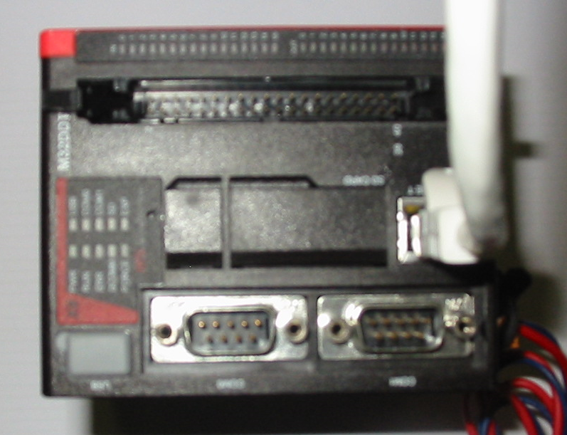 |
| <Figure 4> Appearance of X8 PLC |