PowerTronics PQR Data Read communication driver is the driver to communicate with PQR ( D50, ... ) controller of PowerTronics in U.S.A.
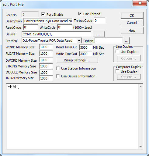
<Figure 1> is read Schedule setting example of PowerTronics PQR Data Read communication driver.
 |
| <Figure 1> Read Schedule setting example of PowerTronics PQR Data Read communication driver |
Device part of <Figure 1> input Com Port(COM1), Baud Rate(19200), Parity Bit(0), Data Bit(8), Stop Bit(1) respectively according to setting of controller.
PowerTronics PQR Data Read communication driverí»s read schedule
PowerTronics PQR Data Read communication driver's read schedule input 'READ' one line.
Communication data for Calibration ASCII data save at STRING memory such as follows :
Status value of complete communication
<Table 1> is contents and address for status value of complete communication.
| Contents | Address | Status value |
| Status value of complete communication | WORD memory address when write setting | 0 = error, 1 = OK ( complete communication ) |
| <Table 1> Contents and address for status value of complete communication | ||
Memory value setting of Communication Server) when you set to 'Extra1 = #mem#' at Analog/Digital output Tag of SCADA Server, you can change memory value forcefully.
You can set PowerTronics PQR controller by using 'write settings'.
Digital Write
Digital write setting parameters are as follows:
1) PORT Port no. (0 ~ 255)
2) STATION don't care.
3) ADDRESS memory address.
CLR_STR command : start STRING memory address to be clear,
other command : WORD memory address for status value of complete communication.
4) Extra1 write command.
CALI : Cailbration start command,
STOP : Cailbration stop command,
DATA : Data Log reading command,
C_DATA : Change Data Logger saving interval setting, ( among 1 second, 5 second, 10 second, 30 second, 1 minute, 4 minute, refer to <Table 2> ),
DETAIL : Detail Report reading command,
SUMMARY : Summary Report data reading command,
CLEAR : Clear Data ( clear saved all data ) command,
TIME : time syncronization with computer,
CLR_STR : String memory clear command ( form Address, size = setting value of Extra2 ).
5) Extra2 data saving file number or size for String memory clear.
CLR_STR – size for String memory clear,
DATA, DETAIL, SUMMARY : data saving file number, ( refer to <Table 3> )
other command : don't care.
Output value |
saving interval |
1 |
1 second |
2 |
5 second |
0, 3 |
10 second |
4 |
30 second |
5 |
1 minute |
6 |
4 minute |
| <Table 2> Output value and saving interval for C_DATA command | |
| Write command | Filename | Remark |
| DATA | work floder\SCAN\LOG_%03d.txt | %03d = 0 ~ 999, value of Extra2 |
| DETAIL | work floder\SCAN\DETAIL_%03d.txt | |
| SUMMARY | work floder\SCAN\SUMMARY_%03d.txt | |
| <Table 3> Filename for data saving write command | ||
Write example 1)
PORT:0, station:0, ADDRESS:0000, Extra1:CLAI, Extra2 :
The setting parameter shown above is Cailbration start command example.
After writing, the status value of complete communication save at 0 WORD memory. ( 0 = error, 1 = OK )
Write example 2)
PORT:0, station:0, ADDRESS:0001, Extra1:STOP, Extra2 :
The setting parameter shown above is Cailbration stop command example.
After writing, the status value of complete communication save at 1 WORD memory. ( 0 = error, 1 = OK )
Write example 3)
PORT:0, station:0, ADDRESS:0002, Extra1:DATA, Extra2 : 1
The setting parameter shown above is Data Log reading command example.
After writing, the readed Data Log save at 'work floder\SCAN\LOG_001.txt' file.
Also, the status value of complete communication save at 2 WORD memory. ( 0 = error, 1 = OK )
Write example 4)
PORT:0, station:0, ADDRESS:0003, Extra1:C_DATA, Extra2 :
The setting parameter shown above is Data Logger saving interval setting example. ( setting( output ) value = refer to <Table 2> )
After writing, the status value of complete communication save at 3 WORD memory. ( 0 = error, 1 = OK )
Write example 5)
PORT:0, station:0, ADDRESS:0004, Extra1:DETAIL, Extra2 : 2
The setting parameter shown above is Detail Report reading command example.
After writing, the readed Detail Report save at 'work floder\SCAN\DETAIL_002.txt' file.
Also, the status value of complete communication save at 4 WORD memory. ( 0 = error, 1 = OK )
Write example 6)
PORT:0, station:0, ADDRESS:0005, Extra1:SUMMARY, Extra2 : 3
The setting parameter shown above is Summary Report data reading command example.
After writing, the readed Summary Report data save at 'work floder\SCAN\SUMMARY_003.txt' file.
Also, the status value of complete communication save at 5 WORD memory. ( 0 = error, 1 = OK )
Write example 7)
PORT:0, station:0, ADDRESS:0006, Extra1:CLEAR, Extra2 :
The setting parameter shown above is Clear all saved log data setting example.
After writing, the status value of complete communication save at 6 WORD memory. ( 0 = error, 1 = OK )
Write example 8)
PORT:0, station:0, ADDRESS:0007, Extra1:TIME, Extra2 :
The setting parameter shown above is time syncronization with computer example.
After writing, the status value of complete communication save at 7 WORD memory. ( 0 = error, 1 = OK )
Write example 9)
PORT:0, station:0, ADDRESS:0000, Extra1:CLR_STR, Extra2 : 201
The setting parameter shown above is String memory clear setting example for 0 ~ 200 String memory.
Analog Write
Analog write and digital write have the same setting parameters except output value.
Connection of main power and communication cable are as follows:
Connection of main power
Please connect 990 ~ 260V AC to main power connector such as <Figure 2>.
 |
| <Figure 2> Connection example of main power and communication cable to PowerTronics controller |
Connection of communication cable
Please connect normal RS-232C communication cable to 9 pin socket of
PowerTronics controller
such as <Figure 2>.
<Figure 3> is appearance of PowerTronics controller.
 |
| <Figure 3> Appearance of PowerTronics controller |