Power Logic SY/MAX communication driver is the driver to communicate with Power Logic Circuit Monitor(2000 Series) of Schneider Electric.
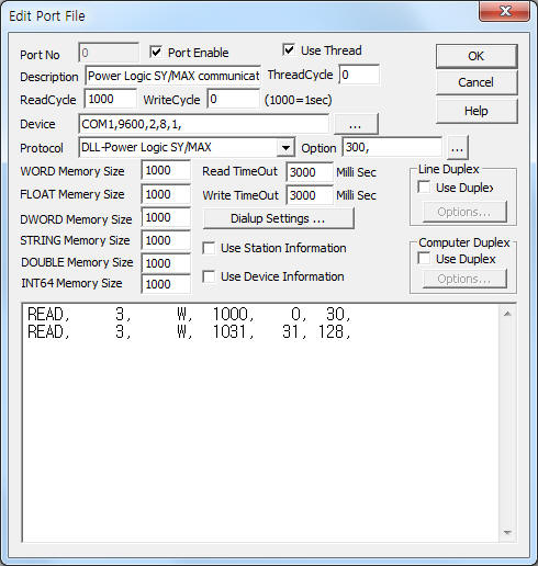
<Figure 1> is read Schedule setting example of Power Logic SY/MAX communication driver.
 |
| <Figure 1> Read Schedule setting example of Power Logic SY/MAX communication driver |
Device part of <Figure 1> input Com Port(COM1), Baud Rate(9600), Parity Bit(2), Data Bit(8), Stop Bit(1) respectively according to setting of controller.
Also input 'delay time after write'( 0 ~ 10000 milli seconds, default : 300), 'additional Route address'( format = 100.15, ... number of maximum Route = 7, default : none ) by using option part. Each argument of option part is a comma-delimited.
Note) Baud rate of Power Logic SY/MAX controller can set 1200 ~ 19200, parity bit, data bit, stop bit are fixed to 2, 8, 1.
Power Logic SY/MAX communication driver’s read schedule
Read schedule setting parameters are as follows:
1) STATION – 0 ~ 255 station number of controller.
2) Read data type – BCD, F, W.
BCD : word data by BCD format,
F : float data( convert float from 2word data ),
W, ... : word data.
3) Read start address – 1 ~ 32767 start reading register number.
4) Save Start Address for Communication Server – Input save start address of communication server.
5) Read Size – 1 ~ 128 word or 1 ~ 64 float read size.
Read schedule example)
READ, 3, W, 1000, 0, 30,
READ, 3, W, 1031, 31, 128,
<Table 1> is data format and type of Power Logic SY/MAX communication driver.
Data format |
Read/Write data type |
Remarks |
word unit |
W |
address ⅹ 2 word value, hex-decimal unit |
BCD format word |
BCD |
address ⅹ 2 word value, decimal unit ( BCD ) |
float unit |
F |
address ⅹ 2 double word value to float by IEEE format |
| <Table 1> Data format and type of Power Logic SY/MAX communication driver | ||
Power Logic SY/MAX communication driver store the same data in WORD, DWORD, FLOAT memory, but the data format are different.
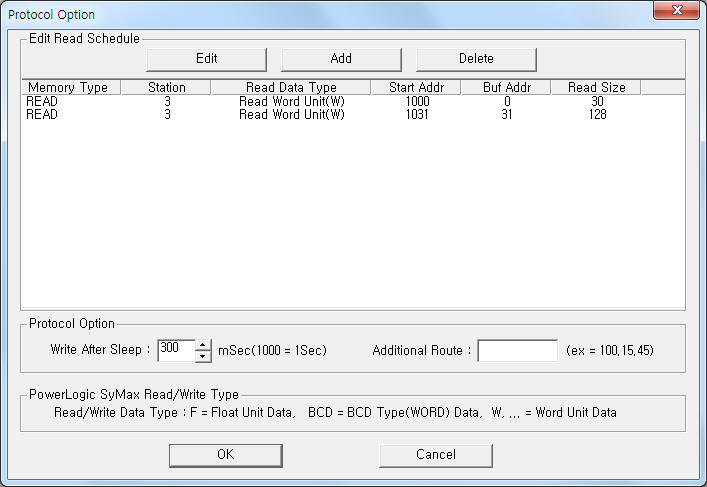
If you click the icon ![]() in protocol option part, you
can see the dialog box such as <Figure 2>. you can also set read schedule by
using this part.
in protocol option part, you
can see the dialog box such as <Figure 2>. you can also set read schedule by
using this part.
 |
| <Figure 2> Example of Power Logic SY/MAX communication driver’s Option dialog box |
You can set read schedule by using ![]() ,
, ![]() ,
, ![]() button and listbox of <Figure
2>.
button and listbox of <Figure
2>.
Also, you can set delay time after write and additional Route address by using the part of ‘Write After Sleep’, 'Additional Route' shown in <Figure 2>.
 |
| <Figure 3> Example of Power Logic SY/MAX communication driver’s read schedule Add/Edit dialog box |
When you click Add button or Edit button in dialog box of <Figure 2>, dialog box of <Figure 3> is shown.
You can set the register value by using write settings.
Digital Write
Digital write setting parameters are as follows:
1) PORT Port no. (0 ~ 255)
2) STATION 0 ~ 255 station number of controller.
3) ADDRESS writing register address.
higher 1 ~ 5 digit : decimal word unit register address,
lower 1 digit : 0 ~ F writing bit position.
4) Extra1 fixed to W or other character = word unit data.
5) Extra2 Don't care.
Note) Digital write support by bit operation after reading the corresponding register.
Write example 1)
PORT:0, station:4, ADDRESS:2001F, Extra1: W, Extra2 :
The setting parameter shown above is a control( On/Off ) example for F bit, 2001 word register ( real address = 4000 ), 4 station number Power Logic SY/MAX controller. (by bit operation after reading the corresponding register )
Analog Write
Analog write setting parameters are as follows:
1) PORT Port no. (0 ~ 255)
2) STATION 0 ~ 255 station number of controller.
3) ADDRESS decimal unit writing register address.
4) Extra1 Writing data type = BCD, F, W.
BCD : word data by BCD format,
F : float data( convert float from 2word data ),
W, ... : word data.
5) Extra2 Don't care.
Write example 1)
PORT:0, station:4, ADDRESS:2001, Extra1: W, Extra2 :
The setting parameter shown above is word unit data setting example for 2001 word register ( real address = 4000 ), 4 station number Power Logic SY/MAX controller.
Write example 2)
PORT:0, station:4, ADDRESS:2001, Extra1: BCD, Extra2 :
The setting parameter shown above is BCD word unit data setting example for 2001 word register ( real address = 4000 ), 4 station number Power Logic SY/MAX controller.
Write example 3)
PORT:0, station:4, ADDRESS:2001, Extra1: F, Extra2 :
The setting parameter shown above is float unit data( 2 word ) setting example for 2001 ~ 2002 word register ( real address = 4000 ), 4 station number Power Logic SY/MAX controller.
Connection of communication cable and main power are as follows:
Connection of communication cable
Please connect RS-485 communication cable to RS-485 IN+, IN-, OUT+, OUT- connector such as <Figure 4>.
Power Logic SyMax RS-485 connector RS-485 of computer
IN + connector----------------------------------- Tx+
IN - connector----------------------------------- Tx-
OUT + connector--------------------------------- Rx+
OUT - connector--------------------------------- Rx-
<Figure 5> is appearance of Power Logic controller.
 |
| <Figure 4> Connection example of main power and communication cable to Power Logic controller |
 |
| <Figure 5> Appearance of Power Logic controller |
Connection of main power
Please connect 220V AC main power to L, N connector of Power Logic controller such as <Figure 4>.
Power Logic controller can set station number, ... by using setting button of front panel. ( refer to <Figure 5> )
1) Press ‘MODE’ button for a while. Then, will be entered to 'Setup' menu and displayed 'Confi9' at screen.
2) Press ‘PHASE’ button at Setup menu. Then, will be entered to 'Password' setting menu.
3) Input Password by using 'Up', 'Down' button ( default password : 0 ) and press ‘PHASE’ button. ( enter to setting mode )
4) Please select 'Address' by pressing ‘PHASE’ button several times. ( will be displayed current Address at screen )
5) Select station address by using 'Up', 'Down' button.
6) Press ‘MODE’ button after setting station address. Then, will be displayed ‘Accept’, ‘no’ menu at screen.
7) Change the character to 'yes' and press ‘PHASE’ button. Then, completed station address setting. ( after setting, automatically reset )


