PLC-BUS Controller communication driver
PLC-BUS Controller is the driver to communicate with Power Line Communication Bus equipments.
1. Read settings
<Figure 1> is PLC-BUS Controller communication driver’s read setting examples.
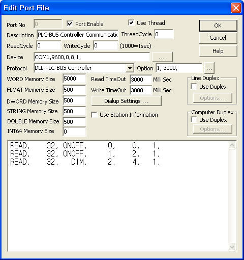 |
| <Figure 1> PLC-BUS Controller communication driver’s read setting examples |
<Figure 1> is the screen where Com Port(COM1), Baud Rate(9600), Parity Bit(0), Data Bit(8), Stop Bit(1) are input in DEVICE.
Also whether to save/load WORD memory when uninit/init(0: disable, 1 : enable, default =10) and receive code check time(0 ~ 65535mSec, default =3000) are set by using option part.
Option part of each argument is a comma-delimited.
PLC-BUS Controller communication driver’s read schedule
Read schedule setting parameters are as follows:
1) STATION – input 0 ~ 255 User Code.
2) Read command – command = ONOFF, DIM, BRIGHT. (refer to <Table 1>)
3) Home/Unit No – 0 ~ 10 = A1 ~ A11 Home/Unit, 16 ~ 26 = B1 ~ B11 Home/Unit, ..., 160 ~ 170 = K1 ~ K11 Home/Unit.
4) Save Start Address for Communication Server – Input save start address of communication server.
5) Read Size – Fixed the read size = 1, then save 2 WORD data.
Read schedule example
READ, 32, ONOFF, 0, 0, 1,
READ, 32, ONOFF, 1, 2, 1,
READ, 32, DIM, 2, 4, 1,
inportant) PLC-BUS Controller communication driver read current status after write rather than read request.
<Table 1> is a description of read command types and stored values of PLC-BUS Controller communication driver.
| Read Command | Content | Store Values | Remarks |
| ONOFF | read Home/Unit status | Start Addr + 0 : On/Off status (0 = Off, 100 = On) Start Addr + 1 : On/Off status 2 |
PLC-BUS Controller communication driver read current value after write rather than read request. |
| DIM | read Dimmer value | Start Addr + 0 : Dimmer value 1 Start Addr + 0 : Dimmer value 2 |
|
| BRIGHT | read Bright value | Start Addr + 0 : Bright value 1 Start Addr + 1 : Bright value 2 |
|
| <Table 1> Read command types and stored values of PLC-BUS Controller communication driver | |||
If you click the icon ![]() in
protocol option part, you can see the dialog box such as <Figure 2>. you can
also set read schedule by using this part.
in
protocol option part, you can see the dialog box such as <Figure 2>. you can
also set read schedule by using this part.
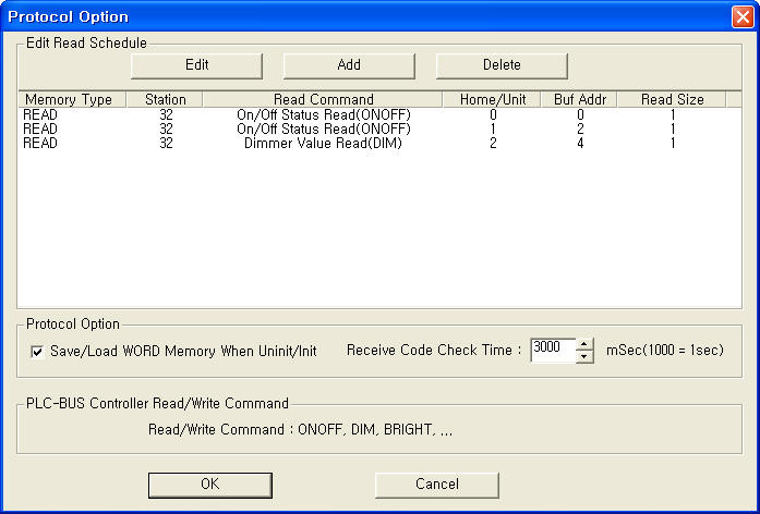 |
| <Figure 2> Example of PLC-BUS Controller communication driver’s Option dialog box |
You can set read schedule by using ![]() ,
, ![]() ,
, ![]() button
and listbox of <Figure 2>.
button
and listbox of <Figure 2>.
Whether to save/load WORD memory when uninit/init and receive code check time are set by using the part of ‘Save/Load WORD Memory When Uninit/Init’ , ‘Receive Code Check Time’ shown in <Figure 2>.
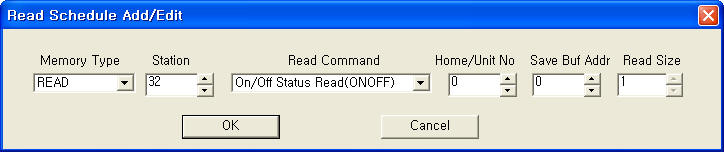 |
| <Figure 3> Example of PLC-BUS Controller communication driver’s read schedule Add/Edit dialog box |
When you click Add button or Edit button in dialog box of <Figure 2>, dialog box of <Figure 3> is shown.
2. Write settings
You can change the setting values of PLC-BUS Controller equipment by using write commands.
Digital Write
Digital write setting parameters are as follows:
1) PORT Port no. (0 ~ 255)
2) STATION 0 ~ 255 User Code.
3) ADDRESS Home/Unit no. 0 ~ 10 = A1 ~ A11 Home/Unit, 16 ~ 26 = B1 ~ B11 Home/Unit, ..., 160 ~ 170 = K1 ~ K11 Home/Unit.
4) Extra1 write command = ONOFF, DIM, BRIGHT. (refer to <Table 2>)
5) Extra2 1 = 3Phase, 0, etc = normal.
Analog Write
Analog write and bit write have the same setting parameters except output value.
<Table 2> is a description of write commands and range of the write value for PLC-BUS Controller communication driver.
| Write Command | Content | range of write value |
| ONOFF | write On/Off of Home/Unit | 10 = On, 0 = Off |
| DIM | write Dimmer value | Dimmer value |
| BRIGHT | write Bright value |
Bright value |
| <Table 2> Write commands and range of the write value for PLC-BUS Controller communication driver | ||
Write example 1)
PORT : 0 STATION : 32 ADDRESS : 0000 EXTRA1 : ONOFF EXTRA2 : 0
The setting parameter shown above is an example of bit write for changing ‘A1 Home/Unit' of PLC-BUS Controller connected with 0 port, set to 32 User Code.
Write example 2)
PORT : 0 STATION : 32 ADDRESS : 0001 EXTRA1 : ONOFF EXTRA2 : 0
The setting parameter shown above is an example of bit write for changing ‘A2 Home/Unit' of PLC-BUS Controller connected with 0 port, set to 32 User Code.
Block Write
PLC_BUS Controller communication driver don’t support ‘Block write’.
3. Serial cable connection of PLC-BUS Controller
You have to connect serial communication cable in the following ways.
Connection of serial communication cable
You can connect serial communication cable that is provided at the time of purchase PLC-BUS Controller to the computer.
<Figure 4> shows the appearance of PLC-BUS Comtroller.
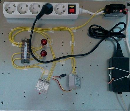 |
| <Figure 4> Appearance of PLC-BUS Controller |