Pine View communication driver is the driver to communicate with temperature measurement controller of PineSys Co., Ltd. in Korea.
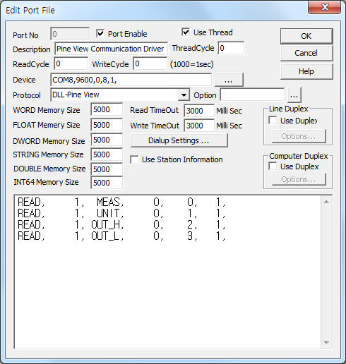
<Figure 1> is read setting example of Pine View communication driver.
|
|
| <Figure 1> Read setting example of Pine View communication driver |
Device part of <Figure 1> input Com Port(COM1), Baud Rate(9600), Parity Bit(0), Data Bit(8), Stop Bit(1) respectively according to setting of controller.
Baud rate, parity bit, stop bit can set by using 'setting button' of Pine View controller or 'Writie settings'.
Pine View communication driver read schedule
Read schedule setting parameters are as follows:
1) STATION – Controller station ID = 1 ~ 127.
2) Read command – Command = MEAS, MANU, INPUT, UNIT, IN_DOT, IN_H, IN_L, D_DOT, D_H, D_L, CORR, HOLD, O_HOLD, FUNC, FILT, A_CH, A_TYPE, A_BAND, A_SET, A_DELAY, BAUD, ID, OUT_H, OUT_L. ( Refer to <Table 1> )
3) Read start address – Don't care.
4) Save Start Address for Communication Server – saveing start address of Communication Server.
5) Read Size – Read size = fixed to 1.
Read schedule example)
READ, 1, MEAS, 0, 0, 1,
READ, 1, UNIT, 0, 1, 1,
READ, 1, OUT_H, 0, 2, 1,
READ, 1, OUT_L, 0, 3, 1,
<Table 1> is contents and range for each read/write command.
<Table 2> is input type and range for INPUT read/write.
| Command | Contents | Remarks |
| MEAS | Read of input measurement value(PV) | Read only |
| MANU | Read of manufacturer | |
| INPUT | Read/write of input type | Refer to <Table 2> |
| UNIT | Read/write of display unit | 0 = ℃, 1 = ℉ |
| IN_DOT | Read/write of input value dot position | 0 = Don't use dot, 1 ~ 3 = 1 ~ 3 digit dot |
| IN_H | Read/write of input value high limit | word unit |
| IN_L | Read/write of input value low limit | |
| D_DOT | Read/write of display value dot position | 0 = Don't use dot, 1 ~ 3 = 1 ~ 3 digit dot |
| D_H | Read/write of display value high limit | word unit |
| D_L | Read/write of display value low limit | |
| CORR | Read/write of sensor correction value | |
| HOLD | Read/write of Hold status | 0 = Off, 1 = minimum value, 2 = maximum value |
| O_HOLD | Read/write of Hold On/Off status | 0 = Off, 1 = On |
| FUNC | Read/write of special function type | 0 = Linear, 2 = Square Root, 3 = Root |
| FILT | Read/write of filter setting | 0 = filter Off, 1 = average filter, 2 = EIR filter1, 3 = EIR filter2 |
| A_CH | Read/write of alarm channel number | 0 ~ 3 = alarm channel 1 ~4 |
| A_TYPE | Read/write of alarm type | 0 = high alarm, 1 =low alarm |
| A_BAND | Read/write of alarm Deadband | 0 ~ 9999 |
| A_SET | Read/write of alarm setting | -1999 ~ 9999 |
| A_DELAY | Read/write of alarm delay time | 0 ~ 9999 |
| BAUD | Read/write of baud rate | 0 = 4800, 1 = 9600, 2 = 19200, 3 = 38400, 4 = 57600 |
| ID | Read/write of station ID | 1 ~ 127 |
| OUT_H | Read/write of output value high limit | word unit |
| OUT_L | Read/write of output value low limit | |
| <Table 1> Contents and range for each read/write command | ||
| Group | Input type | Range of Read/write value range |
| TC | B (PR 30%) | 0 |
| R (PR 13%) | 1 | |
| S (PR 10%) | 2 | |
| K (CA) | 3 | |
| E (CRC) | 4 | |
| J (IC) | 5 | |
| T (CC) | 6 | |
| N | 7 | |
| mV | 11 | |
| RTD | DIN PT100 Ω | 8 |
| DIN (0.1) PT | 9 | |
| JIS PT100 Ω | 10 | |
| mA | V | 12 |
| mV | 13 | |
| <Table 2> Input type and range for INPUT read/write | ||
If you click the icon ![]() in protocol option part, you
can see the dialog box such as <Figure 2>. you can also set read schedule by
using this part.
in protocol option part, you
can see the dialog box such as <Figure 2>. you can also set read schedule by
using this part.
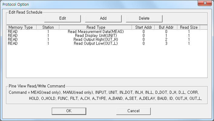 |
| <Figure 2> Example of Pine View communication driver’s Option dialog box |
You can set read schedule by using ![]() ,
, ![]() ,
, ![]() button and listbox of <Figure
2>.
button and listbox of <Figure
2>.
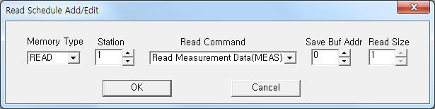 |
| <Figure 3> Example of Pine View communication driver’s read schedule Add/Edit dialog box |
When you click Add button or Edit button in dialog box of <Figure 2>, dialog box of <Figure 3> is shown.
You can write setting value of temperature controller by using write settings.
Digital Write
Digital write and Analog write have the same setting parameters except output value(0 or 1).
Analog Write
Analog write setting parameters are as follows:
1) PORT Port no. (0 ~ 255)
2) STATION Controller station ID number = 1 ~ 127.
3) ADDRESS Don't care.
4) Extra1 Write command = INPUT, UNIT, IN_DOT, IN_H, IN_L, D_DOT, D_H, D_L, CORR, HOLD, O_HOLD, FUNC, FILT, A_CH, A_TYPE, A_BAND, A_SET, A_DELAY, BAUD, ID, OUT_H, OUT_L. ( Refer to <Table 1> )
5) Extra2 Don't care.
Write example 1)
PORT:0, station:1, ADDRESS:0000, Extra1: INPUT, Extra2 :
The setting parameter shown above is input type(output range = 0 ~ 13) setting example of 1 station ID Pine View controller.
Write example 2)
PORT:0, station:1, ADDRESS:0000, Extra1: IN_DOT, Extra2 :
The setting parameter shown above is input value dot position(output range = 0 ~ 3) setting example of 1 station ID Pine View controller.
Connection of communication cable and main power are as follows.
Connection of RS-485 communication cable
Please connect RS-485 communication cable to 11(+), 12(-) connector of Pine View controller.
Connection of main power
Please connect 85 ~ 264V AC main power to 26, 27 connector.
<Figure 4> is appearence of Pine View controller.
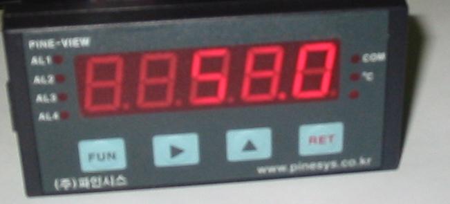 |
| <Figure 4> Appearence of Pine View controller |