PCL812PG communication driver is the driver to communicate with input/output card of Advantech Co., Ltd. in Taiwan.
Note) PCL812PG card must install at computer by ISA or PCI card type.
PCL812PG card have 16 channel analog input, 2 channel analog output, 16 channel digital input, 16 channel digital output, 3 Counter/Timer.
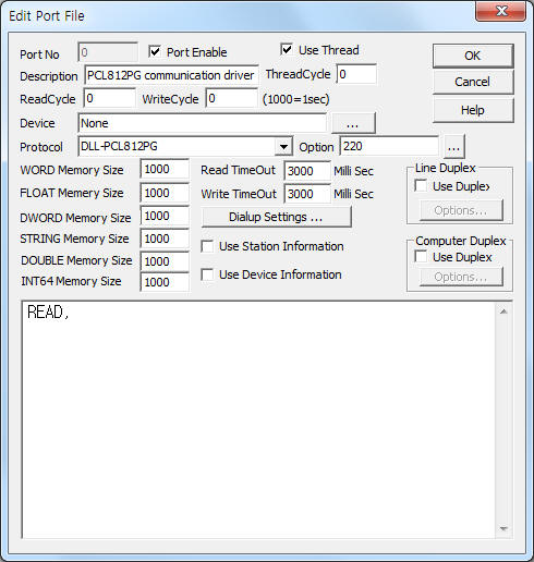
<Figure 1> is read setting example of PCL812PG communication driver.
 |
| <Figure 1> Read setting example of PCL812PG communication driver |
Device part of <Figure 1> input 'None'.
In protocol option, you can set 'I/O memory address of PCL812PG card'( 200 ~ 2F0 : can set by DIP switch ).
PCL812PG communication driverí»s read schedule
Read schedule of PCL812PG communication driver input 'READ' one line.
Readed data of PCL812PG communication driver save at 0 ~ 23 WORD memory such as follows :
0 ~ 2 : Counter / Timer data (16 bit size : 0 ~ 65535 or 0 ~ 9999),
3 : Counter / Timer control register.
4 ~ 19 : analog input 16 channel data (12 bit size : 0 ~ 4095),
20 ~ 21 : analog output 2 channel data(12 bit size : 0 ~ 4095),
22 : digital input 16 channel data,
23 : digital output 16 channel data.
You can control PCL812PG output card by using 'write settings'.
Digital Write
Digital write setting parameters are as follows:
1) PORT Port no. (0 ~ 255)
2) STATION don't care.
3) ADDRESS writing address in digital output = 0230 ~ 023F.
4) Extra1 don't care.
5) Extra2 don't care.
Write example 1)
PORT : 0 , STATION : 0, ADDRESS : 023F, EXTRA1 : , EXTRA2 :
The setting parameter shown above is digital control( On/Off ) example for F ( 16th ) address digital output.
Analog Write
Analog write setting parameters are as follows:
1) PORT Port no. (0 ~ 255)
2) STATION don't care.
3) ADDRESS writing address in counter or analog output = 0000 ~ 0003, 0020 ~ 0021.
4) Extra1 don't care.
5) Extra2 don't care.
Write example 1)
PORT : 0 , STATION : 0, ADDRESS : 0021, EXTRA1 : , EXTRA2 :
The setting parameter shown above is analog value setting( 0 ~ 4095 ) example to 1 ( 2nd ) address analog output.