PCD S-BUS Ethernet communication driver is the driver to communicate with S-BUS ethernet protocol of Saia-Burgess Controls in Switzerland.
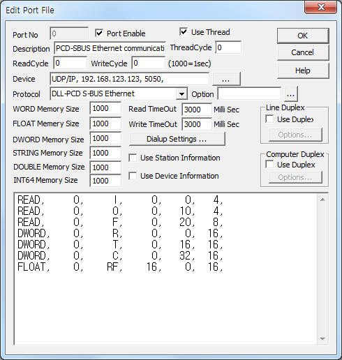
<Figure 1> is read setting example of PCD S-BUS Ethernet communication driver.
 |
| <Figure 1> Read setting example of PCD S-BUS Ethernet communication driver |
Device part of <Figure 1> input Device type(UDP/IP), IP address of PLC(192.168.123.123), service port of UDP/IP protocol ( fixed to 5050 ),respectively, according to setting of controller.
In protocol option, you can set 'protocol type of S-BUS'( 0 : Data Mode, 1 : Parity Mode, 2 : Break Mode, default = 0 ), 'delay time when Parity/Break communication mode'( 1 ~ 100 milli second, default = 30 ). Each argument is a comma-delimited.
Note) IP address, station number of PCD controller can set 'Online Configurator' program such as 'Chapter 4'.
PCD S-BUS Ethernet communication driver¡¯s read schedule
Read schedule setting parameters are as follows:
1) Station – PCD S-BUS station number = 0 ~ 253.
2) Read data type – data type = I,O,F,R, RF,T,C. ( refer to <Table 1> )
3) Read Start Address – reading start address in data type.
4) Save start address for Communication Server – Saving start address of Communication Server.
5) Read Size – word or double word / float unit read size.
I,O,F : 1 ~ 16 word ( 16bit unit ),
R,T,C : 1~32 double word or float.
Read schedule example)
READ, 0, I, 0, 0, 4,
READ, 0, O, 0, 10, 4,
READ, 0, F, 0, 20, 8,
DWORD, 0, R, 0, 0, 16,
DWORD, 0, T, 0, 16, 16,
DWORD, 0, C, 0, 32, 16,
FLOAT, 0, RF, 16, 0, 16,
<Table 1> is data type and contents of PCD controller.
Data(memory) type |
Contents |
Units |
Write |
I |
Input |
Bit |
disable |
O |
Output |
enable |
|
F |
Flag |
||
R/RF |
Register |
R = DWORD, RF = FLOAT |
|
T |
Timer |
DWORD |
|
C |
Counter |
DWORD |
|
| <Table 1> Data type and contents of PCD controller | |||
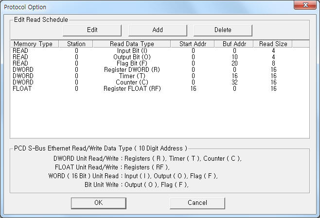
If you click the icon ![]() in protocol option part, you
can see the dialog box such as <Figure 2>. you can also set read schedule by
using this part.
in protocol option part, you
can see the dialog box such as <Figure 2>. you can also set read schedule by
using this part.
 |
| <Figure 2> Example of PCD S-BUS Ethernet communication driver¡¯s Option dialog box |
You can set read schedule by using ![]() ,
, ![]() ,
, ![]() button and listbox of <Figure
2>.
button and listbox of <Figure
2>.
 |
| <Figure 3> Example of PCD S-BUS Ethernet communication driver¡¯s read schedule Add/Edit dialog box |
When you click Add button or Edit button in dialog box of <Figure 2>, dialog box of <Figure 3> is shown.
You can control PCD controller by using 'write settings'.
Digital Write
Digital write setting parameters are as follows:
1) PORT Port no. (0 ~ 255)
2) STATION PCD S-BUS station number = 0 ~ 253.
3) ADDRESS writing address in data type. ( decimal unit including bit, double word data type )
4) Extra1 write data type = O, F, R, RF, T, C.
5) Extra2 don't care.
Write example 1)
PORT : 0 , STATION : 0, ADDRESS : 0015, EXTRA1 : O, EXTRA2 :
The setting parameter shown above is control( On/Off ) example of O0015 address.
Write example 2)
PORT : 0 , STATION : 0, ADDRESS : 0021, EXTRA1 : F, EXTRA2 :
The setting parameter shown above is control( On/Off ) example of F0021 address.
Analog Write
Analog write setting parameters are as follows:
1) PORT Port no. (0 ~ 255)
2) STATION PCD S-BUS station number = 0 ~ 253.
3) ADDRESS writing address in data type. ( decimal unit including bit, double word data type )
4) Extra1 write data type = R, RF, T, C, O, F.
5) Extra2 don't care.
Write example 1)
PORT : 0 , STATION : 0, ADDRESS : 0003, EXTRA1 : R, EXTRA2 :
The setting parameter shown above is dobule word unit write setting example of R0003 address.
Write example 2)
PORT : 0 , STATION : 0, ADDRESS : 0012, EXTRA1 : RF, EXTRA2 :
The setting parameter shown above is float unit write setting example of R0012 address.
Write example 3)
PORT : 0 , STATION : 0, ADDRESS : 0035, EXTRA1 : T, EXTRA2 :
The setting parameter shown above is double word unit write setting example of T0035 address.
Connection of power and communication cable are as follows.
Connection of main power
Please connect 24V DC power to main power connector such as <Figure 4>.
Connect 1st, 2nd pin = +24 V ( 20, 21 two or one ), 3rd, 4th pin = 0 V ( 22, 23 two or one ) from below of main power connector( black socket ).
 |
| <Figure 4> Connection example of main power line and ethernet communication cable to PCD controller |
Connection of ethernet communication cable
Please connect ethernet communication cable to RJ45 ethernet connector such as <Figure 4>.
Setting of S-BUS station number and IP address are as follows.
Setting of S-BUS station number
1) Please run ¡®Online Configurator¡¯ of PG5. Then, will be open 'Saia Online Configurator' dialog box such as <Figure 5>.
2) Select ¡®Hardware Settings¡¦¡¯(Online|Hardware Settings¡¦) menu at <Figure 5>. Then, will be open 'Hardware Settings' dialog box such as <Figure 6>.
3) When you select ¡®S-Bus¡¯ tab at <Figure 6>. Then, will be open S-Bus Setting menu such as <Figure 7>.
 |
| <Figure 5> Example of 'Saia Online Configurator' program |
 |
| <Figure 6> Example of 'Hardware Settings' dialog box |
4) Please input S-BUS address between 0 ~ 253. Click 'OK' button, then will be open 'Download Hardware Settings' dialog box such as <Figure 8>.
5) Click ¡®OK¡¯ button at <Figure 8>. Then, changed S-BUS station number after downloading.
 |
| <Figure 7> S-Bus tab example of 'Hardware Settings' dialog box |
 |
| <Figure 8> Example of 'Download Hardware Settings' dialog box |
Setting of IP address
1) When you select ¡®TCP/IP¡¯ tab at <Figure 6> or <Figure 7>. Then, will be open TCP/IP address setting menu such as <Figure 9>.
2) Input IP address, IP Node, Sub Net Mask, Router at <Figure 9>. Click 'OK' button, then will be open 'Download Hardware Settings' dialog box such as <Figure 8>.
3) Click ¡®OK¡¯ button at <Figure 8>. Then, changed IP address, ...after downloading.
 |
| <Figure 9> TCP/IP tab example of 'Hardware Settings' dialog box |