MET ONE Particle Counter communication driver is the driver to communicate with water quality analyzer of Met One Instruments Inc. in U.S.A.
Note) MET ONE Particle Counter use RS-485 communication. So, you should to install RS-485 communication card or RS-232C to RS-485 Converter at computer.
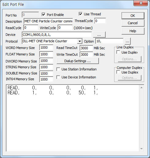
<Figure 1> is read setting example of MET ONE Particle Counter communication driver.
 |
| <Figure 1> Read setting example of MET ONE Particle Counter communication driver |
Device part of <Figure 1> input Com Port(COM1), Baud Rate(9600), Parity Bit(0), Data Bit(8), Stop Bit(1) respectively.
In protocol option, you can set 'Particle Counter data reading period'( time interval of Stop Counting after Start Counting, default = 6 second ).
Note) Baud rate, parity bit, data bit, stop bit of Met One Particle Counter are fixed to 9600, 0, 8, 1.
MET ONE Particle Counter communication driver¡¯s read schedule
Read schedule setting parameters are as follows:
1) Station – controller station number = 0 ~ 63.
2) Read Command – don't care. ( fixed to read of Send Record data )
3) Read Start Address – Don't care.
4) Save start address for Communication Server – Saving start address of Communication Server.
5) Read Size – fixed to 1. ( refer to <Table 1> )
Read schedule example)
READ, 0, 0, 0, 0, 1,
READ, 1, 0, 0, 50, 1,
<Table 1> is data saving address and contents for read command.
Data saving address |
Contents |
Remarks |
Start addr + 0 |
communication status |
32 : normal, 33 : Sensor Fail Alarm, 36 : alarm/count Alarm |
Start addr + 1 ~ 3 |
year, month, day |
|
Start addr + 4 ~ 6 |
hour, minute, second |
|
Start addr + 7 |
sample time or Counting time |
second unit |
Start addr + 8 ~ 9 |
size of range1, count of range1 |
7 ~ 10 Range ( Range 1 ~ 6, Input A, B, Calibration, Location ) |
Start addr + 10 ~ 11 |
size of range2, count of range2 |
|
Start addr + 12 ~ 13 |
size of range3, count of range3 |
|
¡¦ |
¡¦ |
|
| <Table 1> Data saving address and contents for read command( Send Record ) | ||
MET ONE Particle Counter communication driver store the same data in WORD, DWORD, FLOAT, STRING memory, but the data format are different.
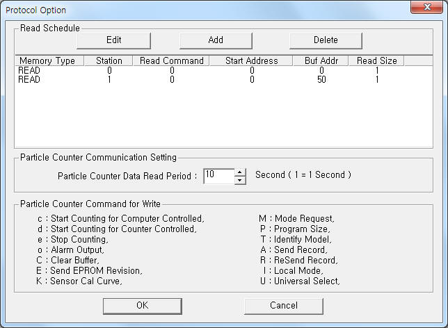
If you click the icon ![]() in protocol option part, you
can see the dialog box such as <Figure 2>. you can also set read schedule by
using this part.
in protocol option part, you
can see the dialog box such as <Figure 2>. you can also set read schedule by
using this part.
 |
| <Figure 2> Example of MET ONE Particle Counter communication driver¡¯s Option dialog box |
You can set read schedule by using ![]() ,
, ![]() ,
, ![]() button and listbox of <Figure
2>.
button and listbox of <Figure
2>.
Also, you can set data reading period of Particle Counter by using the part of ¡®Particle Counter Data Read Period¡¯ shown in <Figure 2>.
 |
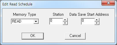
| <Figure 3> Example of MET ONE Particle Counter communication driver¡¯s read schedule Add/Edit dialog box |
When you click Add button or Edit button in dialog box of <Figure 2>, dialog box of <Figure 3> is shown.
You can read, write by using 'write settings'.
Digital Write
Digital write and analog write have the same setting parameters except output value.
Analog Write
Analog write setting parameters are as follows:
1) PORT Port no. (0 ~ 255)
2) STATION controller station number = 0 ~ 63.
3) ADDRESS data saving start address when A, R command. ( decimal unit )
4) Extra1 read or write command. ( refer to <Table 2> )
c, d, e, o, C, E, K, M, P, T, A, R, I, U, ...
5) Extra2 Don't care.
<Table 2> is write command and contents of MET ONE Particle Counter communication driver.
Command |
Contents |
Remarks |
c |
Start Counting ( Computer Controlled ) |
case-sensitive |
d |
Start Counting ( Counter Controlled ) |
|
e |
End Counting |
|
o |
Alarm Output |
|
C |
Clear Buffer |
|
E |
Send EPROM Revision |
|
K |
Send Cal Curve |
|
M |
Mode Request |
|
P |
Program Sizes |
|
T |
Identify Model |
|
A |
Send Record |
|
R |
Re Send Record |
|
I |
Local Mode |
|
U |
Universal Select |
|
| <Table 2> Write command and contents of MET ONE Particle Counter communication driver | ||
Write example 1)
PORT : 0 , STATION : 0, ADDRESS : 0000, EXTRA1 : R, EXTRA2 :
The setting parameter shown above is Re Send Record data reading example of station 0 MET ONE Particle Counter.
After reading, the readed data save at 0 ~ WORD, DWORD, FLOAT, STRING memory.
Write example 2)
PORT : 0 , STATION : 0, ADDRESS : 0000, EXTRA1 : c, EXTRA2 :
The setting parameter shown above is Start Counting control example of station 0 MET ONE Particle Counter.
Write example 3)
PORT : 0 , STATION : 0, ADDRESS : 0000, EXTRA1 : e, EXTRA2 :
The setting parameter shown above is End Counting control example of station 0 MET ONE Particle Counter. ( only when Start Counting )
Write example 4)
PORT : 0 , STATION : 0, ADDRESS : 0100, EXTRA1 : A, EXTRA2 :
The setting parameter shown above is Send Record data reading example of station 0 MET ONE Particle Counter.
After reading, the readed data save at 100 ~ WORD, DWORD, FLOAT, STRING memory. ( after Start Counting, Stop Counting command )
Connection of power and communication cable are as follows.
Connection of power
Please connect DC power to +15V, AGND, -15V, +5V, DGND connector such as <Figure 4>. ( connect power converter provided by Met One : main power = 100 ~ 250 V AC )
 |
| <Figure 4> Connection example of main power line and communication cable to MET ONE Particle Counter |
<Figure 5> shows the appearance of MET ONE Particle Counter.
 |
| <Figure 5> Appearance of MET ONE Particle Counter |
Connection of communication cable
Please connect RS-485 communication cable to 485A( + ), 485B( - ) connector.
RS-485 of computer MET ONE Particle Counter
Tx+, Rx+ -------------------------------------- 485A connector
Tx-, Rx- -------------------------------------- 485B connector
You can set station number of MET ONE Particle Counter by 'HyperTerminal' program.
1) Power off all connected Particle Counter controller.
2) Power on to be set Particle Counter controller.
3) Connect 'HyperTerminal' program by 9600, 0, 8, 1 within 30 seconds after power on.
4) input 'load' and press 'Enter' ket.
5) Then, will be displayed 'setting' menu. ( when don't display 'setting' menu, an error or passed 30 seconds )
6) Select '1' ( Unit ID or station setting, setting menu = 1 ~ 9 ) and set station number.
7) Setting is ended when inputing 'Q' key.