OPTO22 communication driver is the driver to communicate with normal controller of OPTO22 in U.S.A.
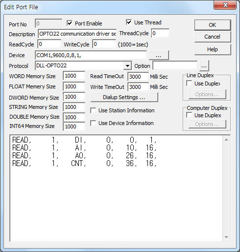
<Figure 1> is read setting example of OPTO22 communication driver.
 |
| <Figure 1> Read setting example of OPTO22 communication driver |
Device part of <Figure 1> input Com Port(COM1), Baud Rate(9600), Parity Bit(0), Data Bit(8), Stop Bit(1) respectively, according to setting of controller.
OPTO22 communication driver read schedule
Read schedule setting parameters are as follows:
1) Station – 0 ~ 255 controller station number, can set by using Group B Pin.
2) Reading module type – module type = DI, AI, AO, CNT.
3) Read start address – don't care.
4) Save start address for Communication Server – Saving start address of Communication Server.
5) Read size – word unit read size. ( 1 = 16 bit when digital module )
Read schedule example)
READ, 1, DI, 0, 0, 1,
READ, 1, AI, 0, 10, 16,
READ, 1, AO, 0, 26, 16,
READ, 1, CNT, 0, 36, 16,
OPTO22 communication driver must set Input, Output status information at ¡®work folder\SCAN\OPTO22.???¡¯ . ( ??? = port number of Communication Server )
Input method = Station, I or O, I or O, , ,
( I = input, O = output module )
Input example)
0, I, I, I, I, O, I, I, I, I, I, I, I, I, I, I, I,
1, O, O, O, O, I, I, I, I, I, I, I, I, I, I, I, I,
3, I, I, I, I, O, O, O, O,
You can set OPTO22 controller by using 'write settings'.
Digital Write
Digital write setting parameters are as follows:
1) PORT Port no. (0 ~ 255)
2) STATION 0 ~ 255 controller station number.
3) ADDRESS 0000 ~ 000F channel number.
4) Extra1 write module type = DO, CONF, CNT, CLR, B, J, k.
5) Extra2 time setting when 'Extra1 = k'. ( 10 mSec unit )
Write example 1)
PORT:0, station:1, ADDRESS:0002, Extra1:DO, Extra2 : 0
The setting parameter shown above is bit write control( On/Off ) example for channel 2, DO module.
Write example 2)
PORT:0, station:1, ADDRESS:0002, Extra1:CONF, Extra2 : 0
The setting parameter shown above is port initialization example for station 1 OPTO22 controller.
Write example 3)
PORT:0, station:1, ADDRESS:0002, Extra1:CNT, Extra2 : 0
The setting parameter shown above is Start(On)/Stop(Off) control example for Pulse Count module.
Write example 4)
PORT:0, station:1, ADDRESS:0002, Extra1:CLR, Extra2 : 0
The setting parameter shown above is Pulse Count value Clear( set to 0 ) example.
Write example 5)
PORT:0, station:1, ADDRESS:0002, Extra1:B, Extra2 : 0
The setting parameter shown above is Pulse Count reset example.
You should to initialize by CONF write command after 'reset' for DO write.
Write example 6)
PORT:0, station:1, ADDRESS:0002, Extra1:k, Extra2 : 200
The setting parameter shown above is Pulse On control example for channel 2 module. Pluse On time = 2 second. ( Extra2 = 10 mSec unit )
Analog Write
Analog write setting parameters are as follows:
1) PORT Port no. (0 ~ 255)
2) STATION 0 ~ 255 controller station number.
3) ADDRESS 0000 ~ 000F channel number.
4) Extra1 write module type = n, J2 or space.
5) Extra2 time setting when 'Extra1 = k'. ( 10 mSec unit )
6) Output value range = 0 ~ 4095
Write example 1)
PORT:0, station:1, ADDRESS:0004, Extra1:, Extra2 : 0
The setting parameter shown above is channel value writing example for channel 4 module.
Write example 2)
PORT:0, station:1, ADDRESS:0004, Extra1:n, Extra2 : 0
The setting parameter shown above is time value changing example for all timing function value of digital brain board.
Output value : 10 mSec unit ( default value = 2.54 second, output value = 2540 mSec )
Write example 3)
PORT:0, station:1, ADDRESS:0000, Extra1:J2, Extra2 : 0
The setting parameter shown above is output status changing example for station 1 OPTO22 controller.
Output value : 0 = all output status 'Off', 5 = 0, 2 bit 'On', 65535 = all output bit 'On'.