NMS Controller Client communication driver is the driver to communicate with NMS system.
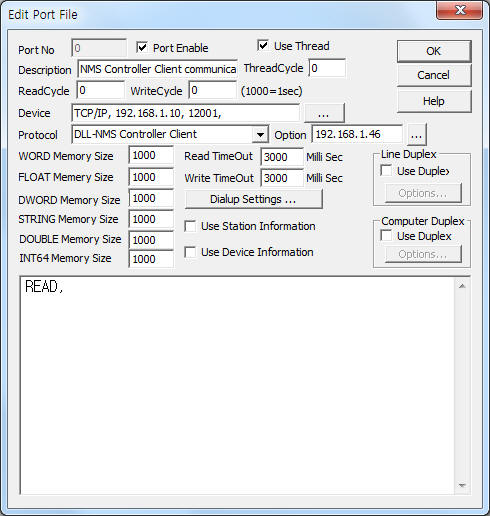
<Figure 1> is read setting example of NMS Controller Client communication driver.
 |
| <Figure 1> Read setting example of NMS Controller Client communication driver |
Device part of <Figure 1> input Device type(TCP/IP), IP address of PLC(192.168.1.10), service port of TCP/IP ( 12001 ),respectively, according to setting of server.
In protocol option part, you can set the IP address( default = 192.168.1.46 ) of client system.
NMS Controller Client communication driver read schedule
NMS Controller Client communication driver's read schedule input 'READ' one line.
Read schedule example)
READ,
NMS Controller Client communication driver receive the server system data by periodically Polling.
<Table 1> is received data saving address and contents of NMS Controller Client communication dirver.
| Received data saving address(WORD memory) | Contents | Range |
| 0 | number of readed Polling packet | 0 ~ 65535 |
| 1 | readed response code | 1 ~ 9999, sequentially increased |
| 2 | hour | 0 ~ 23 |
| 3 | minute | 0 ~ 59 |
| 4 | second | 0 ~ 59 |
| 5 | equipment code | 1 ~ 99 |
| <Table 1> Received data saving address and contents of NMS Controller Client communication dirver | ||
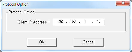
If you click the icon ![]() in protocol option part at
<Figure 1>, you
can see the dialog box such as <Figure 2>. you can also set IP address of
client.
in protocol option part at
<Figure 1>, you
can see the dialog box such as <Figure 2>. you can also set IP address of
client.
 |
| <Figure 2> Example of NMS Controller Client communication driverí»s Option dialog box |
You can set NMS system by using 'write settings'.
Digital Write
Digital write and analog write have the same setting parameters except output value.
Analog Write
Analog write setting parameters are as follows:
1) PORT Port no. (0 ~ 255)
2) STATION decimal unit station / function room code.
higher 2 digit = 1 ~ 99 station code,
lower 2 digit = 1 ~ 99 function room code.
3) ADDRESS decimal unit equipment / failure code.
higher 2 digit = 1 ~ 99 equipment code,
lower 2 digit = 1 ~ 99 failure code.
4) Extra1 input 'ARM.aaaa.bbbb' format.
ARM = command of failure alarm,
aaaa = 1 ~ 9999 decimal unit controller code,
bbbb = 1 ~ 9999 decimal unit failure code.
5) Extra2 detail failure code 1, 2. ( decimal unit number )
higher 2 digit = detail failure code 1,
lower 2 digit = detail failure code 2.
6) Output value 1 = failure alarm, 0 = clear alarm.
After writing, the sended failure code save at 10 ~ 23 WORD memory such as <Table 2>.
<Table 2> is data saving address and contents for ARM write command.
Data saving address (WORD memory) |
Contents |
Range |
10 |
number of failure alarm |
0 ~ 65535 |
11 |
response code |
1 ~ 9999, sequentially increased |
12 ~ 14 |
hour/minute/secind |
|
15 |
station code |
1 ~ 99 |
16 |
function room code |
|
17 |
equipment code |
|
18 |
failure level code |
|
19 |
controller code |
1 ~ 9999 |
20 |
failure code |
|
21 |
detail failure code 1 |
1 ~ 99 |
22 |
detail failure code 2 |
|
23 |
failure alarm/clear alarm |
failure alarm = 0, clear alarm = 99 |
| <Table 2> Data saving address and contents for ARM write command | ||
Write example 1)
PORT:0, station:102, ADDRESS:0304, Extra1: ARM.5.6, Extra2 : 0708
The setting parameter shown above is failure alarm sending example.
The sending value : station code = 1, function room code = 2, equipment code = 3, failure level = 4, controller code = 5, failure code = 6, detail failure code 1 = 7, detail failure code 2 = 8, Output value : 1 = failure alarm, 0 = clear alarm.
After writing, the sended failure code save at 10 ~ 23 WORD memory such as <Table 2>.