NAM IL S-302CR communication driver is the driver to communicate with temperature controller of Namil Engineering in Korea.
Note) For RS-422/485 communication with NAM IL S-302CR controller, you should to use RS-232C To RS-422/485 convert( or RS-422/485 communication card, ... ) at computer. ( recommand T-232 convert of Namil Engineering )
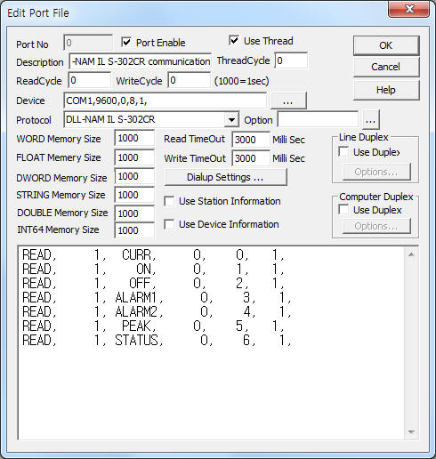
<Figure 1> is read setting example of NAM IL S-302CR communication driver.
 |
| <Figure 1> Read setting example of NAM IL S-302CR communication driver |
Device part of <Figure 1> input Com Port(COM1), Baud Rate(9600), Parity Bit(0), Data Bit(8), Stop Bit(1) respectively.
Note) Baud rate, station of S-302CR controller can set by using front pannel operation switch. ( refer to chapter 4 )
NAM IL S-302CR communication driver read schedule
Read schedule setting parameters are as follows:
1) Station – 0 ~ 255 station number of S-302CR controller.
2) Read command – command = CURR, ON, OFF, ALARM1, ALARM2, PEAK, STATUS. ( refer to <Table 1> )
3) Read start address – don't care.
4) Save start address for Communication Server – Saving start address of Communication Server.
5) Read size – fixed to 1 or 3. ( STATUS command = fixed to 3 )
Read schedule example)
READ, 1, CURR, 0, 0, 1,
READ, 1, ON, 0, 1, 1,
READ, 1, OFF, 0, 2, 1,
READ, 1, ALARM1, 0, 3, 1,
READ, 1, ALARM2, 0, 4, 1,
READ, 1, PEAK, 0, 5, 1,
READ, 1, STATUS, 0, 6, 1,
<Table 1> is read, write command contents of NAM IL S-302CR communication driver.
<Table 2> is data saving address and contents for STATUS command.
Read, write command |
Contents |
Remarks |
CURR |
Current Temperature |
read only |
ON |
Fan On Temperature |
read/write |
OFF |
Fan Off Temperature |
|
ALARM1 |
Alarm1 Temperature |
|
ALARM2 |
Alarm2 Temperature |
|
PEAK |
Peak Temperature |
|
STATUS |
Auto/Manual, Buzzer, Error Status |
refer to <Table 2> |
| <Table 1> Read/write command contents of NAM IL S-302CR communication driver | ||
Data saving address |
Contents |
Range |
Remarks |
Start addr + 0 |
auto/manual status |
1 = Auto, 0 = Manual |
write enable |
Start addr + 1 |
buzzer status |
0 = No Alarm, 1 = Alarm1, 2 = Alarm2, 3 = Alarm 1,2 |
|
Start addr + 2 |
error status |
0 = Normal, 0, 1 Bit ON ( 3 ) = E01, 0, 2 Bit ON ( 5 ) = E02, 0, 3 Bit ON ( 9 ) = Sensor re-setting |
|
| <Table 2> Data saving address and contents for STATUS command | |||
If you click the icon ![]() in protocol option part at
<Figure 1>, you
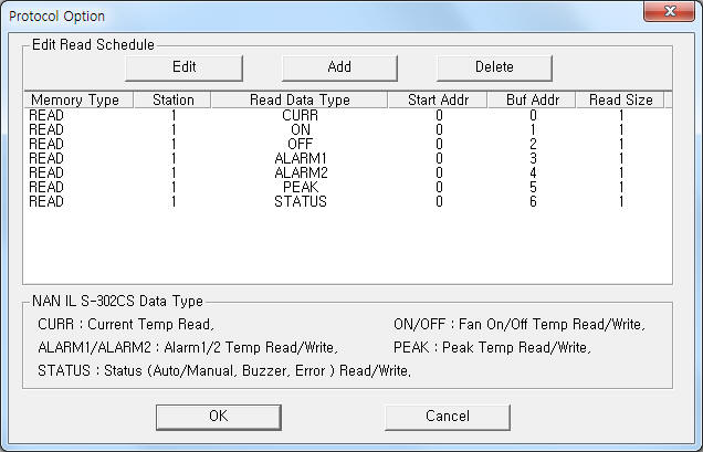
can see the dialog box such as <Figure 2>. you can also set read schedule by
using this part.
in protocol option part at
<Figure 1>, you
can see the dialog box such as <Figure 2>. you can also set read schedule by
using this part.
 |
| <Figure 2> Example of NAM IL S-302CR communication driverí»s Option dialog box |
You can set read schedule by using ![]() ,
, ![]() ,
, ![]() button and listbox of <Figure
2>.
button and listbox of <Figure
2>.
 |
| <Figure 3> Example of NAM IL S-302CR communication driverí»s read schedule Add/Edit dialog box |
When you click Add button or Edit button in dialogue box of <Figure 2>, dialogue box of <Figure 3> is shown.
You can set NAM IL S-302CR controller by using 'write settings'.
Digital Write
Digital write and analog write have the same setting parameters except output value.
Analog Write
Analog write setting parameters are as follows:
1) PORT Port no. (0 ~ 255)
2) STATION 0 ~ 255 station number of S-302CR controller.
3) ADDRESS don't care.
4) Extra1 write command = ON, OFF, ALARM1, ALARM2, PEAK, STATUS. ( refer to <Table 1>, <Table 2> )
5) Extra2 auto, manual selection when STATUS write command. ( auto = 1, manual = 0 )
Write example 1)
PORT:0, station:1, ADDRESS:0000, Extra1: ON, Extra2 : 0
The setting parameter shown above is fan On temperature setting example of station 1 S-302CR controller.
Write example 2)
PORT:0, station:1, ADDRESS:0000, Extra1: OFF, Extra2 : 0
The setting parameter shown above is fan Off temperature setting example of station 1 S-302CR controller.
Write example 3)
PORT:0, station:1, ADDRESS:0000, Extra1: ALARM1, Extra2 : 0
The setting parameter shown above is alarm 1 setting temperature control example of station 1 S-302CR controller.
Write example 4)
PORT:0, station:1, ADDRESS:0000, Extra1: STATUS, Extra2 : 1, Output value = 3
The setting parameter shown above is 'auto and buzzer enable for alarm 1 and 2' control example of station 1 S-302CR controller. ( refer to <Table 2> )
Write example 5)
PORT:0, station:1, ADDRESS:0000, Extra1: STATUS, Extra2 : 0, Output value = 1
The setting parameter shown above is 'manual and buzzer enable for alarm 1' control example of station 1 S-302CR controller. ( refer to <Table 2> )
Connection of main power and communication cable are as follows:
Connection of main power
Please connect 85 ~ 265V AC main power to 25, 26 connector such as <Figure 4>.
<Figure 4> is connection example of main power and communication cable to S-302CR controller.
 |
| <Figure 4> Connection example of main power and communication cable to S-302CR controller |
Connection of communication cable
Please connect RS-485 communication cable to 18( + ), 17( - ) connector of S-302CR controller such as <Figure 4>.
RS-485 of computer S-302 controller
Tx+, Rx+ ------------------------------------------ 18 connector
Tx-, Rx- ------------------------------------------- 17 connector
RS-232C to RS-485 Converter
Normally, to communication with NAM IL S-302CR controller, it needs RS-232C To RS-422/485 convert such as <Figure 5>.
 |
| <Figure 5> RS-232C to RS-485 Converter of Namil Engineering |
<Figure 6> is appearance of S-302CR controller.
 |
| <Figure 6> Appearance of S-302CR controller |
Setting of station and baud rate are as follows:
Setting of station
You can set station number by using front panel button such as follows.
1) Press 'PROG' button while 3 seconds. Then will be displayed 'Setting menu' for Fan On temperature.
2) Press 4 times 'PGOG' button. Then, changes to setting menu of 'station'.
3) Please select 0 ~ 255 station number by using 'Up', 'Down' button.
Setting of baud rate
You can set baud rate by using front panel button such as follows.
1) Press 'PROG' button while 3 seconds. Then will be displayed 'Setting menu' for Fan On temperature.
2) Press 5 times 'PGOG' button. Then, changes to setting menu of 'baud rate'.
3) Please select 2400 ~ 9600 baud rate by using 'Up', 'Down' button.