Mini-Convectron Module communication driver is the driver to communicate with Dual Process Relays of Helix Technology Corporation in U.S.A.
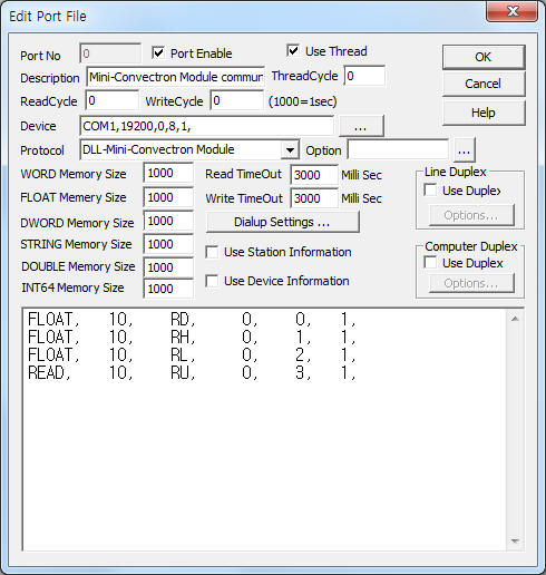
<Figure 1> is read setting example of Mini-Convectron Module communication driver.
 |
| <Figure 1> Read setting example of Mini-Convectron Module communication driver |
Device part of <Figure 1> input Com Port(COM1), Baud Rate(19200), Parity Bit(0), Data Bit(8), Stop Bit(1) respectively, according to setting of controller.
Note) Baud rate, parity bit, data bit, stop bit of Mini-Convectron Module can set by using SB, SPN, SPO, SPE, RST write command.
Mini-Convectron Module communication driver read schedule
Read schedule setting parameters are as follows:
1) Station – 0 ~ 255 station number. DIP switch address(0 ~ 15) + address Offset by SA write command.
2) Read command – command = RD, RH, RL, VER, RU. ( refer to <Table 1> )
3) Read start address – don't care.
4) Save start address for Communication Server – Saving start address of Communication Server.
5) Read Size – fixed to 1.
Read schedule example)
FLOAT, 10, RD, 0, 0, 1,
FLOAT, 10, RH, 0, 1, 1,
FLOAT, 10, RL, 0, 2, 1,
READ, 10, RU, 0, 3, 1,
<Table 1> is read command and contents of Mini-Convectron Module communication driver.
| Read command | Contents | Saving data |
| RD | Read Pressure | pressure value(FLOAT data) |
| RH | Read Set Point 2 | Set Point 2 value(FLOAT data) |
| RL | Read Set Point 1 | Set Point 1 value(FLOAT data) |
| VER | Read Firmware Version | version of firmware (also, save STRING memory ) |
| RU | Read Unit of Measure | uint of measure(also, save STRING memory ) 1 = MBAR, 2 = PASCAL, 4 = TORR, 128 = other |
| <Table 1> Read command and contents of Mini-Convectron Module communication driver | ||
Mini-Convectron Module communication driver store the same data in WORD, DWORD, FLOAT, STRING( only VER, RU command ) memory, but the data format are different.
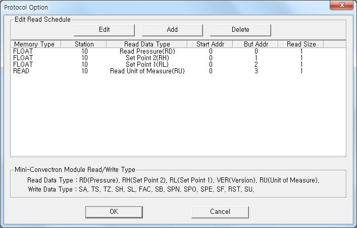
If you click the icon ![]() in protocol option part at
<Figure 1>, you
can see the dialogue box such as <Figure 2>. you can also set read schedule by
using this part.
in protocol option part at
<Figure 1>, you
can see the dialogue box such as <Figure 2>. you can also set read schedule by
using this part.
 |
| <Figure 2> Example of Mini-Convectron Module communication driverí»s Option dialog box |
You can set read schedule by using ![]() ,
, ![]() ,
, ![]() button and listbox of <Figure
2>.
button and listbox of <Figure
2>.
 |
| <Figure 3> Example of Mini-Convectron Module communication driverí»s read schedule Add/Edit dialog box |
When you click Add button or Edit button in dialogue box of <Figure 2>, dialogue box of <Figure 3> is shown.
You can set Mini-Convectron Module by using 'write settings'.
Digital Write
Digital write and analog write have the same setting parameters except output value.
Analog Write
Analog write setting parameters are as follows:
1) PORT Port no. (0 ~ 255)
2) STATION 0 ~ 255 station number. DIP switch address(0 ~ 15) + address Offset by SA write command.
3) ADDRESS writing status saving memory address when TS, TZ command.
4) Extra1 write command = SA, TS, TZ, SH, SL, FAC, SB, SPN, SPO, SPE, SF, RST, SU. ( refer to <Table 2>, <Table 3> )
5) Extra2 don't care.
<Table 2> is write command and contents of Mini-Convectron Module communication driver.
<Table 3> is writing status value and contents for status write command.
Write command |
Contents |
Output range |
SA |
Set Address Offset |
0 ~ 240 |
TS |
Set Span |
FLOAT value |
TZ |
Set Zero |
|
SH |
Set point 2 Write |
|
SL |
Set point 1 Write |
|
FAC |
Set Factory Default |
none |
SB |
Set Baud Rate |
1 = 300 bps, 2 = 1200 bps, 3 = 2400 bps, 4 = 4800 bps, 5 = 9600 bps, 6 = 19200 bps, 7 = 38400 bps, other = 19200 bps |
SPN |
Set Parity NONE, Data Bit 8 |
none |
SPO |
Set Parity ODD, Data Bit 7 |
|
SPE |
Set Parity EVEN, Data Bit 7 |
|
SF |
Set Frequency |
1 ~ 120 Hz |
RST |
Reset Module |
none |
SU |
Set Unit of Measure |
1 = MBAR, 2 = PASCAL, 4 = TORR |
| <Table 2> Write command and contents of Mini-Convectron Module communication driver | ||
| Write command | Status value |
Contents |
| TS | 1 |
normal status(PROGM OK) |
2 |
HI ATM V |
|
4 |
LO ATM V |
|
8 |
GAIN LIM |
|
16 |
DEF SNSR |
|
32 |
RANGE ER |
|
128 |
other |
|
| TZ | 1 |
normal status(PROGM OK) |
2 |
HI VAC V |
|
4 |
LO VAC V |
|
8 |
OFST LIM |
|
16 |
DEF SNSR |
|
32 |
RANGE ER |
|
128 |
other |
|
| <Table 3> Writing status value and contents for status write command | ||
Write example 1)
PORT:0, station:10, ADDRESS:0000, Extra1: SA, Extra2 : 0
The setting parameter shown above is Address Offset(0 ~ 240) writing example of station 10 Mini-Convectron module.
Address Offset changed when the module is reset. ( also after RST command )
Write example 2)
PORT:0, station:10, ADDRESS:0000, Extra1: FSA, Extra2 : 0
The setting parameter shown above is Factory Default setting example of station 10 Mini-Convectron module.
Factory Default applied when the module is reset. ( also after RST command )
Factory Default value : Base Address = 01, Zero/Span ░¬ = Default, A/D frequency = 60Hz, Baud Rate = 19200, Data Format = 8 Bit, no parity, 1 stop bit.
Write example 3)
PORT:0, station:10, ADDRESS:0000, Extra1: SF, Extra2 : 0
The setting parameter shown above is Frequency( 1 ~ 120 ) setting example of station 10 Mini-Convectron module.
Write example 4)
PORT:0, station:10, ADDRESS:0000, Extra1: SU, Extra2 : 0, Output value = 1
The setting parameter shown above is Pressure Units of Measure setting( to MBAR unit ) example of station 10 Mini-Convectron module.
Connection of communication cable and main power are as follows:
Connection of communication cable
Please connect RS-485 communication cable to 1( + ), 2( - ) pin.
15 pin socket of Mini-Convectron RS-485 of computer
1 (+) pin -------------------------- + connector
2 (-) pin -------------------------- - connector
<Figure 4> is appearance of Mini-Convectron module.
 |
| <Figure 4> Appearance of Mini-Convectron module |
Connection of main power
Please connect 11 ~ 26.5V DC main power to 3( + ), 4( - ) pin of 15 pin socket.