Micro Jet Recorder communication driver is the driver to communicate with recorder controller of Fuji Electric Co., Ltd. in Japan.
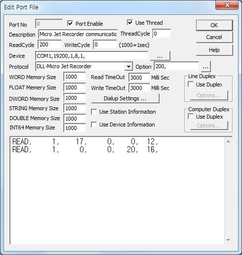
<Figure 1> is read setting example of Micro Jet Recorder communication driver.
 |
| <Figure 1> Read setting example of Micro Jet Recorder communication driver |
Device part of <Figure 1> input Com Port(COM1), Baud Rate(19200), Parity Bit(1), Data Bit(8), Stop Bit(1) respectively, according to setting of controller. ( setting of switch )
Also you can set 'write after waiting time'( 0 ~ 5000 mSec, default = 200) by using option part.
Micro Jet Recorder communication driver read schedule
Read schedule setting parameters are as follows:
1) Station – 0 ~ 31 station number.
2) Read file number – 0 ~ 127 file number. ( refer to <Table 1> )
3) Read start address – 0 ~ 255 reading start address in file.
4) Save start address for Communication Server – Saving start address of Communication Server.
5) Read Size – 1 ~ 16 word.
Read schedule example)
READ, 1, 17, 0, 0, 12,
READ, 1, 0, 0, 20, 16,
<Table 1> is ile number and contents of Micro Jet Record communication driver.
Please refer to User manual for more information of file number and contents.
File number |
Contents |
Read/Write |
Size |
0 |
Parameter |
read/write |
16 word |
1 ~ 12 |
Range |
each 32 word |
|
13 |
Alarm Setting |
144 word |
|
14 |
System |
32 word |
|
15 |
Command |
8 word |
|
16 |
Input Failure Information |
read only |
6 word |
17 |
Input Data |
12 word |
|
19 |
Alarm Output |
36 word |
|
21 |
Transmission Input Data |
write only |
12 word |
22 |
Message |
read/write |
120 word |
33 ~ 35 |
Daily Report |
read only |
each 256 word |
37 ~ 38 |
Totalization |
||
| <Table 1> File number and contents of Micro Jet Record communication driver | |||
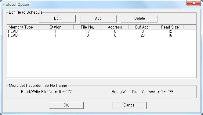
If you click the icon ![]() in protocol option part at
<Figure 1>, you
can see the dialogue box such as <Figure 2>. you can also set read schedule by
using this part.
in protocol option part at
<Figure 1>, you
can see the dialogue box such as <Figure 2>. you can also set read schedule by
using this part.
 |
| <Figure 2> Example of Micro Jet Recorder communication driver¡¯s Option dialog box |
You can set read schedule by using ![]() ,
, ![]() ,
, ![]() button and listbox of <Figure
2>.
button and listbox of <Figure
2>.
 |
| <Figure 3> Example of Micro Jet Recorder communication driver¡¯s read schedule Add/Edit dialog box |
When you click Add button or Edit button in dialogue box of <Figure 2>, dialogue box of <Figure 3> is shown.
You can control Micro Jet Recorder by using 'writing settings'.
Digital Write
Digital write and analog write have the same setting parameters except output value.
Analog Write
Analog write setting parameters are as follows:
1) PORT Port no. (0 ~ 255)
2) STATION 0 ~ 31 station number.
3) ADDRESS writing start address in file.
0 ~ 511 byte(decimal) unit address when Extra2 = '1',
0 ~ 255 word(decimal) unit address when Extra2 not equal '1'.
4) Extra1 0 ~ 127 file number. ( refer to <Table 1> )
5) Extra2 writing data type setting.
1 = byte unit ,
0, ... = word unit.
Note) Byte unit write of Micro Jet Recorder communication driver has developed word unit write after reading that address and byte(word) data operation.
Write example 1)
PORT:0, station:1, ADDRESS:0000, Extra1: 0, Extra2 : 0
The setting parameter shown above is word value writing example of file 0, address 0.
Write example 2)
PORT:0, station:1, ADDRESS:0002, Extra1: 15, Extra2 : 1
The setting parameter shown above is byte value writing example of file 15, address 2.
Connection of communication cable and main power are as follows:
Connection of communication cable
Please connect RS-485 communication cable to TRX1( + ), TRX2( - ) connector.
Micro Jet Recorder ( COMM ) RS-485 of computer
TRX1( + ) connector---------------------------- + connector
TRX2( - ) connector---------------------------- - connector
<Figure 4> is connection example of communication cable and main power to Micro Jet Recorder.
 |
| <Figure 4> Connection example of communication cable and main power to Micro Jet Recorder |
Connection of main power
Please connect 200 ~ 240V AC 50/60 HZ main power to AC input connector such as <figure 4>.
Note) On/Off switch of Micro Jet Recorder be inside of front display area.
Station of Micro Jet Recorder can set 0 ~ 31. Also, baud rate, parity bit, data bit, stop bit are can set as follows:
1) Please open front cover at operation(run) status. You can see Selsec, Up, Down, Entry button at the right side.
2) Press 12 times 'Selsect' button. Then will be displayed ¡®COMMUNICATION¡¯( up ) and ¡®STATION NO.¡¯ ( down ) at display screen.
3) Please select 0 ~ 31 station number by using Up, Down button and press Entry button. Then, will be displayed ¡®BAUD RATE¡¯ at display screen.
4) Select baud rate among 2400, 4800, 9600, 19200 by using Up, Down button and press ENTRY button. Then, will be displayed ¡®STOP BIT¡¯ at display screen.
5) Please select stop bit(1 or 2) by using Up, Down button and press ENTRY button. Then, will be displayed ¡®PARITY¡¯ at display screen.
6) Select parity bit(None, Odd, Even) by using Up, Down button and press ENTRY button. Then, will displayed ¡®DATA TYPE¡¯ at display screen.
7) Press ENTRY button again. Then will be displayed ¡®COMMUNICATION¡¯ at display screen.
8) Press ¡®DISPLAY¡¯ button. Then will be entered to operation(run) mode.
<Figure 5> is appearance of Micro Jet Recorder.
 |
| <Figure 5> Appearance of Micro Jet Recorder |