MelSer I/O J4 Series is the driver to communicate with AC Servo J4 series of Mitsubishi Electric in Japan.
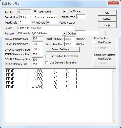
<Figure 1> is read setting example of MelSer I/O J4 Series communication driver.
|
|
| <Figure 1> Read setting example of MelSer I/O J4 Series communication driver |
Device part of <Figure 1> input Com Port( COM7 ), Baud rate( 19200 ), Parity Bit ( 2 ), Data Bit ( 8 ), Stop Bit ( 1 ) respectively, accordint to the setting of controller.
Read schedule of MelSer I/O J4 Series communication driver
Read schedule setting parameters are as follows:
1) station – 0 ~ 31 station number.
2) read command – Command : STS, ALARM, G_PARA, CURR, HIGH, LOW, ABB, WRITE, IO, H_ALM, S_ALM, TEST ( refer to <Table 1> ). Also you can input 0 ~ FF command number.
3) data number – 0 ~ 255 data number.
4) Save start address for Communication Server – Saving start address of Communication Server.
5) Read size – fixed to 1.
Read schedule example)
READ, 1, CURR, 1, 0, 1,
READ, 1, CURR, 2, 1, 1,
READ, 1, CURR, 3, 2, 1,
READ, 1, IO, 0, 3, 1,
READ, 1, ALARM, 0, 5, 1,
<Table 1> is read command and readed data saving value for MelSer I/O J4 Series communication driver.
Read Command |
Contents |
Data saving value for Communication Server |
Data Number | Remarks |
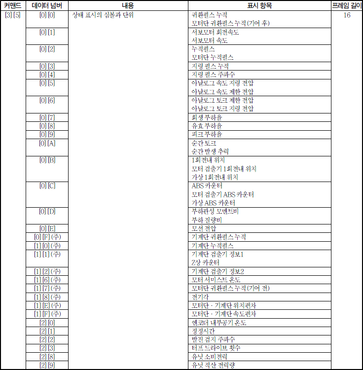
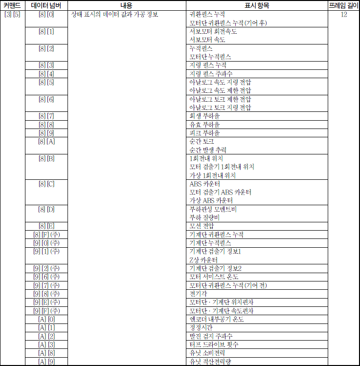
STS |
read of status display data |
Saving Start Address + 0 : unit Saving Start Address + 1 : name |
0 ~ 41 | save only STRING memory |
Saving Start Address + 0 : status data value |
128 ~ 169 | value | ||
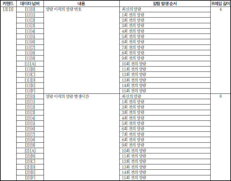
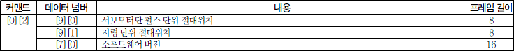
ALARM |
read of current alarm number or other status value |
Saving Start Address + 0 : readed value |
1 : alarm number 112 : software version 144 : absolute position by pulse unit 145 :absolute position by instruction unit |
save only STRING memory when software version read |
G_PARA |
read of parameter group number |
Saving Start Address + 0 : Parameter number |
fixed to 1 | 0 : default setting parameter([Pr.PA_ _ ]) 1 : gain filter parameter([Pr.PB_ _ ]) 2 : extended setting parameter([Pr.PC_ _ ]) 3 : I/O setting parameter([Pr.PD_ _ ]) 4 : extended setting2 parameter([Pr.PE_ _ ]) 5 : extended setting3 parameter([Pr.PF_ _ ]) 11 : linear servo motor/DD motor setting parameter([Pr.PL_ _ ]) |
CURR |
read of parameter value |
Saving Start Address + 0 : current value |
1 ~ 255 | |
HIGH |
high limit setting value of parameter |
Saving Start Address + 0 : high limit value |
1 ~ 255 | |
LOW |
low limit setting value of parameter |
Saving Start Address + 0 : low limit value |
1 ~ 255 | |
ABB |
abbreviation string read for each parameter |
Saving Start Address + 0 : abbreviation string |
1 ~ 255 | save only STRING memory |
WRITE |
read of writable value for each parameter |
Saving Start Address + 0 : writable/not writable |
1 ~ 255 | 0 = writable, 1 = not writable |
IO |
read of external I/O signal |
Saving Start Address + 0 : I/O signal High 16 bit Saving Start Address + 1 : I/O signal Low 16 bit |
0 : Input device status 64 : external Input pin status 96 : Input device status by communication 'ON' 128 : Output device status 192 : external output pin status |
status value for each 32 bit |
H_ALM |
read of history alarm value |
Saving Start Address + 0 : history alarm value |
16 ~ 47 | |
S_ALM |
read of status display when alarm status |
Saving Start Address + 0 : status display value |
0 ~ 41 | save only STRING memory |
Saving Start Address + 0 : status data value |
128 ~ 169 | value | ||
TEST |
read of test running mode |
Saving Start Address + 0 : running mode value |
fixed to 18 | 0 : normal mode( not test run ) 1 : JOG run 2 : direction decision run 3 : not exist motor run 4 : compulsion DO output |
| <Table 1> Read command and readed data saving value for MelSer I/O J4 Series communication driver | ||||
MelSer I/O J4 Series communication driver store the same data in WORD, DWORD, FLOAT memory, but the data format are different.
However, STS( 0 ~ 41 data number ), ABB, S_ALM( 0 ~ 41 data number ) read command save only STRING memory.
If you click the icon ![]() in protocol option part at
<Figure 1>, you
can see the dialog box such as <Figure 2>. you can also set read schedule by
using this part.
in protocol option part at
<Figure 1>, you
can see the dialog box such as <Figure 2>. you can also set read schedule by
using this part.
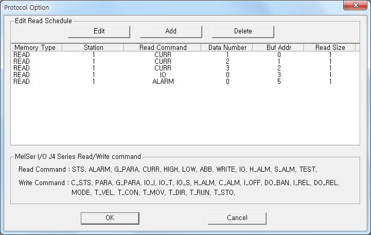 |
| <Figure 2> Example of MelSer I/O J4 Series communication driver’s Option dialog box |
You can set read schedule by using
![]() ,
,
![]() ,
,
![]() button and listbox of <Figure
2>.
button and listbox of <Figure
2>.
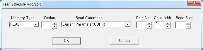 |
| <Figure 3> Example of MelSer I/O J4 Series communication driver’s read schedule Add/Edit dialog box |
When you click Add button or Edit button in dialogue box of <Figure 2>, dialogue box of <Figure 3> is shown.
You can control MelSer I/O J4 Series by using 'write settings'.
Digital Write
Digital write and analog write have the same setting parameters except output value.
Analog Write
Analog write setting parameters are as follows:
1) PORT Port no. (0 ~ 255)
2) Station 0 ~ 31 station number.
3) Address 0 ~ 255 data number when PARA write command, etc command : don't care.
4) Extra1 Write command : C_STS, PARA, G_PARA, IO_I, IO_T, IO_S, H_ALM, C_ALM, I_OFF, DO_BAN, I_REL, DO_REL, MODE, T_VEL, T_CON, T_MOV, T_DIR, T_RUN, T_STO ( refer to <Table 2> ).
5) Extra2 write mode and dot position of output value when PARA write command.
write mode : 10 digit - 1 = write to EEP-ROM,
0 = write to RAM,
dot : 0 = integer, 1 ~ 4 = dot 1 ~ 4 digit.
<Table 2> is write command and output value for MelSer I/O J4 Series for communication driver.
Write command |
Contents |
Data number | Output value |
C_STS |
delete of status display data |
fixed to 0 | fixed to 1EA5h ( always delete regardless of output value ) |
PARA |
write of each parameter value |
1 ~ 255 | number value ( Extra2 = write mode and dot position of write value ) |
G_PARA |
write of parameter group number |
fixed to 0 | 0 : default setting parameter([Pr.PA_ _ ]) 1 : gain filter parameter([Pr.PB_ _ ]) 2 : extended setting parameter([Pr.PC_ _ ]) 3 : I/O setting parameter([Pr.PD_ _ ]) 4 : extended setting2 parameter([Pr.PE_ _ ]) 5 : extended setting3 parameter([Pr.PF_ _ ]) 11 : linear servo motor/DD motor setting parameter([Pr.PL_ _ ]) |
IO_I |
write of communication input device signal |
fixed to 96 | output for each 32 bit status |
IO_T |
write of input signal when test mode |
fixed to 0 | output for each 32 bit status |
IO_S |
write of compulsion output value for signal pin |
fixed to 160 | output for each 32 bit status |
H_ALM |
delete od history alarm |
fixed to 32 | fixed to 1EA5h ( always delete regardless of output value ) |
C_ALM |
delete of current alarm data |
fixed to 0 | fixed to 1EA5h ( always delete regardless of output value ) |
I_OFF |
OFF command for input device, external analog input signal, pulse input except EM2, LSP and LSN |
fixed to 0 | fixed to 1EA5h ( always OFF regardless of output value ) |
DO_BAN |
output prohibit command for all DO |
fixed to 3 | fixed to 1EA5h ( always prohibit regardless of output value ) |
I_REL |
prohibit release command for input device, external analog input signal, pulse input except EM2, LSP and LSN |
fixed to 16 | fixed to 1EA5h ( always prohibit release regardless of output value ) |
DO_REL |
output prohibit release command for DO |
fixed to 19 | fixed to 1EA5h ( always prohibit release regardless of output value ) |
MODE |
setting command running mode |
fixed to 0 | 0 : release of test run mode 1 : JOG run mode 2 : direction decision run mode 4 : compulsion DO output |
T_VEL |
write of rotational speed for test mode |
fixed to 16 | 0 ~ 7FFFh (32767 ) |
T_CON |
write of acceleration and deceleration constant |
fixed to 17 | 0 ~ 7FFFFFFFh |
T_MOV |
write of movement amount for test mode |
fixed to 32 | 0 ~ 7FFFFFFFh |
T_DIR |
direction command for test mode |
fixed to 33 | 0 : instruction pulse unit, forward rotation 1 : instruction pulse unit, reverse rotation 256 : encorder pulse unit, forward rotation 257 : encorder pulse unit, reverse rotation |
T_RUN |
run command for test mode |
fixed to 64 | fixed to 1EA5h ( always delete regardless of output value ) |
T_STO |
pause, restart, clear command for test mode |
fixed to 65 | 0 : pause 1 : restart of remaining distance 2 : clear of remaining distance |
| <Table 2> Write command and output value for MelSer I/O J4 Series for communication driver | |||
Write example 1)
PORT : 0 STATION : 1 ADDRESS : 0001 EXTRA1 : PARA EXTRA2 : 0
The setting parameter shown above is current parameter setting example for data number 1, station 1.
( write mode = write to RAM, dot = 0 )
Write example 2)
PORT : 0 STATION : 1 ADDRESS : 0002 EXTRA1 : PARA EXTRA2 : 11
The setting parameter shown above is current parameter setting example for data number 2, station 1.
( write mode = write to EEP-ROM, dot = 1 )
Write example 3)
PORT : 0 STATION : 1 ADDRESS : 0000 EXTRA1 : G_PARA EXTRA2 : 0 Output value = 0
The setting parameter shown above is parameter group setting example to default ( 0 ) setting parameter.
<Figure 4> shows the appearance of MelSer I/O J4 controller.
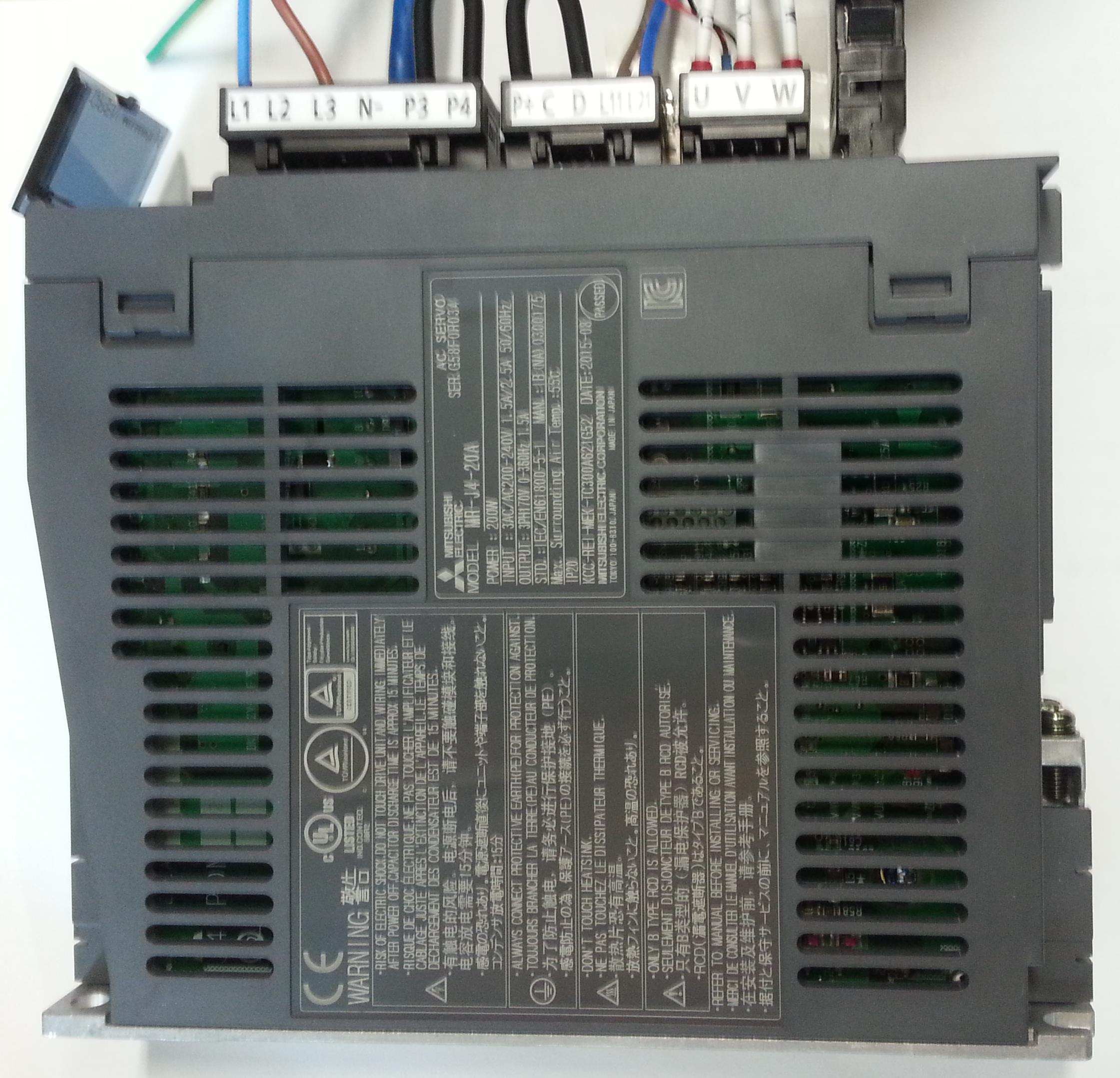 |
| <Figure 4> Appearance of MelSer I/O J4 controller |
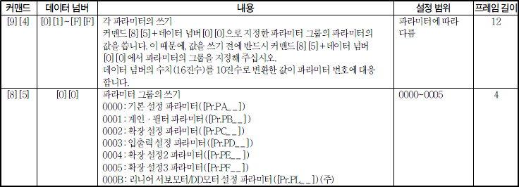
<Figure 5> is command, data number and contents for read command of MelSer I/O J4 Series communication driver.
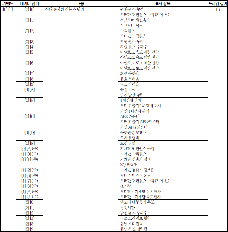 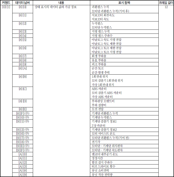 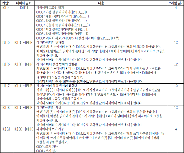 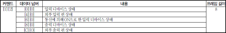      |
| <Figure 5> Command, data number and contents for read command of MelSer I/O J4 Series communication driver |
<Figure 6> is command, data number and contents for write command of MelSer I/O J4 Series communication driver
 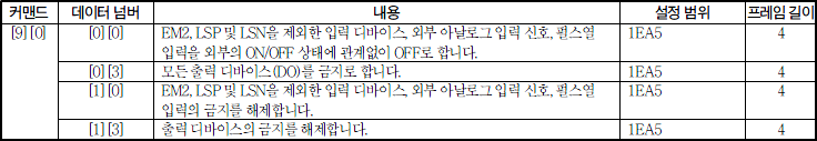 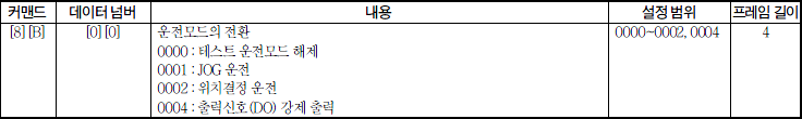 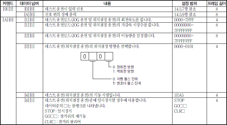 |
| <Figure 6> Command, data number and contents for write command of MelSer I/O J4 Series communication driver |