Megatec Extended Communication driver is the driver to communicate with Three-Phase UPS of Mega System Technologies,Inc. in Taiwan.
Note) G1, G2, G3, GF read command can communicate when using 3 phase connection.
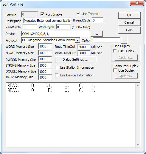
<Figure 1> is read setting example of Megatec Extended communication driver.
 |
| <Figure 1> Read setting example of Megatec Extended communication driver |
Device part of <Figure 1> input Com Port(COM1), Baud Rate(2400), Parity Bit(0), Data Bit(8), Stop Bit(1) respectively. ( fixed to 2400, 0, 8, 1 )
Megatec Extended communication driver read schedule
Read schedule setting parameters are as follows:
1) Station – don't care.
2) Read command – Command = G1, G2, G3, GF, I, F, Q1.
G1 = read of UPS Read Time Data,
G2 = UPS Status Inquiry,
G3 = read of UPS Realtime Data 3 Phases,
GF = read of UPS Rating Information,
I = read of UPS Information,
F = read of UPS Rating Information,
Q1 = Status Inquiry.
3) Read start address – don't care.
4) Save start address for Communication Server – Saving start address of Communication Server.
5) Read Size – fixed to 1.
Read schedule example)
READ, 0, Q1, 0, 0, 1,
READ, 0, F, 0, 10, 1,
<Table 1> is read command and contents of Megatec Extended communication driver.
| Read command | Contents | Data saving address | Range | Remarks |
| G1 | read of UPS Read Time Data |
Start addr + 0 : Battery voltage Start addr + 1 : Battery Capacity percentage Start addr + 2 : Battery Time Remaining Start addr + 3 : Battery current in charge mode or discharge mode Start addr + 4 : Temperature(Degree of centigrade) Start addr + 5 : . I/P frequency Start addr + 6 : Frequency of Bypass Source Start addr + 7 : O/P frequency |
0 ~ 999 0 ~ 100 0 ~ 9999 0.0 ~ 999.9 –99.9 ~ +99.9 0.0 ~ 99.9 0.0 ~ 99.9 0.0 ~ 99.9 |
|
| G2 | UPS Status Inquiry |
Start addr + 0 : The Status of Rectifier and DC Start addr + 1 : The Status of UPS Start addr + 2 : The Fault Condition of Inverter |
refer to <Table 2> ~ <Table 4> |
|
| G3 | read of UPS Realtime Data 3 Phases |
Start addr + 0 ~ 2 : . I/P voltage of R/S/T 3 ╗ˇ Start addr + 3 ~ 5 : Bypass AC source voltage of R/S/T 3 ╗ˇ Start addr + 6 ~ 8 : O/P voltage of R/S/T 3 ╗ˇ Start addr + 9 ~ 11 : Load percentage of R/S/T 3 ╗ˇ |
0.0 ~ 999.0 |
|
| GF | read of UPS Rating Information |
Start addr + 0 : Rectifier Voltage of Phase to Neutral and Phase to Phase Start addr + 1 : Rectifier Frequency Start addr + 2 : Bypass Source Voltage of Phase to Neutral and Phase to Phase Start addr + 3 : Bypass Source Frequency Start addr + 4 : O/P Voltage of Phase to Neutral and Phase to Phase Start addr + 5 : O/P Frequency Start addr + 6 : Battery Voltage Start addr + 7 : Power_Rating |
14 digit string 0 ~ 999 14 digit string 0 ~ 999 14 digit string 0 ~ 999 0 ~ 999 10 digit string |
save at STRING memory |
| I | read of UPS Information |
Start addr + 0 : company name, UPS model, Version information |
string |
save at STRING memory |
| F | read of UPS Rating Information |
Start addr + 0 : Rating Voltage Start addr + 1 : Rating Current Start addr + 2 : Battery Voltage Start addr + 3 : Frequency |
0.0 ~ 999.9 0 ~ 999 0.0 ~ 999.9 0.0 ~ 99.9 |
|
| Q1 | Status Inquiry |
Start addr + 0 : I/P voltage Start addr + 1 : I/P fault voltage Start addr + 2 : O/P voltage Start addr + 3 : O/P current Start addr + 4 : I/P frequency Start addr + 5 : Battery voltage Start addr + 6 : Temperature Start addr + 7 : UPS Status |
0.0 ~ 999.9 0.0 ~ 999.9 0.0 ~ 999.9 0 ~ 999 0.0 ~ 99.9 0.0 ~ 99.9 0.0 ~ 99.9 refer to <Table 5> |
|
| <Table 1> Read command and contents of Megatec Extended communication driver | ||||
| Bit position | Contents |
| 7 | don't use |
| 6 | RECTIFIER ROTATION ERROR |
| 5 | 1 : Low
|
| 4 | 1 : Low
|
| 3 | 1 : Three in –One out 0 : three in –Three out |
| 2 | 1 : Back Up0 : AC Normal |
| 1 | 1 : Boost Charge0 : Float Charge |
| 0 | 1 : Rectifier Operating |
| <Table 2> Each bit meaning for the status of Rectifier and DC | |
| Bit position | Contents |
| 7 | No Use |
| 6 | No Use |
| 5 | No Use |
| 4 | BYPASS FRQUENCY FAIL |
| 3 | 1 : Manual Bypass Breaker On 0 : Manual Bypass Breaker Open |
| 2 | 1 : Bypass AC Normal 0 : Bypass AC Abnormal |
| 1 | 1 : Static Switch in Inverter Mode 0 : Static Switch in Bypass Mode |
| 0 | 1 : Inverter Operating |
| <Table 3> Each bit meaning for the status of UPS | |
| Bit position | Contents |
| 7 | No Use |
| 6 | 1 : Emergency Stop (EPO) |
| 5 | 1 : High DC Shutdown |
| 4 | 1 : Manual Bypass Breaker on Shutdown |
| 3 | 1 : Over Load Shutdown |
| 2 | 1 : Inverter O/P Fail Shutdown |
| 1 | 1 : Over Temperature Shutdown |
| 0 | 1 : Short Circuit Shutdown |
| <Table 4> Each bit meaning for the Fault Condition of Inverter status | |
| Bit position | Contents |
| 7 | 1 : Utility Fail (Immediate) |
| 6 | 1 :
|
| 5 | 1 : Bypass/Boost or Buck Active |
| 4 | 1 : UPS Failed |
| 3 | 0 : UPS Type is Online (1 is Standby) |
| 2 | 1 : Test in Progress |
| 1 | 1 : Shutdown Active |
| 0 | 1 : Beeper On |
| <Table 5> Each bit meaning for UPS status | |
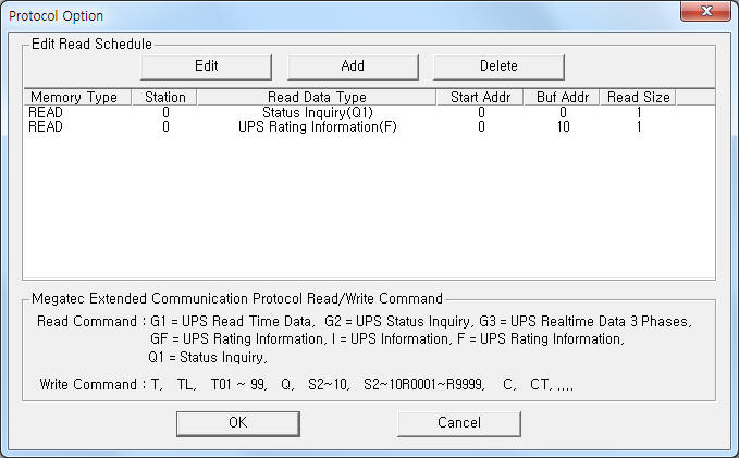
If you click the icon ![]() in protocol option part at
<Figure 1>, you
can see the dialogue box such as <Figure 2>. you can also set read schedule by
using this part.
in protocol option part at
<Figure 1>, you
can see the dialogue box such as <Figure 2>. you can also set read schedule by
using this part.
 |
| <Figure 2> Example of Megatec Extended communication driverí»s Option dialog box |
You can set read schedule by using ![]() ,
, ![]() ,
, ![]() button and listbox of <Figure
2>.
button and listbox of <Figure
2>.
 |
| <Figure 3> Example of Megatec Extended communication driverí»s read schedule Add/Edit dialog box |
When you click Add button or Edit button in dialogue box of <Figure 2>, dialogue box of <Figure 3> is shown.
You can control Megatec Extended controller by using 'writing settings'.
Digital Write
Digital write and analog write have the same setting parameters except output value.
Analog Write
Analog write setting parameters are as follows:
1) PORT Port no. (0 ~ 255)
2) STATION don't care.
3) ADDRESS don't care.
4) Extra1 write command.
T = 10 Seconds Test,
TL
= Test until
T<n> = Test for Specified Time Period, <n> : 01 ~ 99,
Q = Turn On/Off beep,
S<n> = Shut Down Command, <n> : 01 ~ 10,
S<n>R<m> = Shut Down and Restore Command, <n> : 01 ~ 10, <m> : 0001 ~ 9999,
C = Cancel Shut Down Command,
CT = Cancel Test Command.
5) Extra2 don't care.
Write example 1)
PORT:0, station:1, ADDRESS:0000, Extra1: T, Extra2 : 0
The setting parameter shown above is 10 Seconds Test control example.
Write example 1)
PORT:0, station:1, ADDRESS:0000, Extra1: Q, Extra2 : 0
The setting parameter shown above is Turn On/Off beep control example.
Please connect RS-232C cable to Tx, Rx, GND connector connector of Megatec Extended UPS.
Computer Megatec Extended UPS
RX ------------------------ TX (pin 9)
TX ------------------------ RX (pin 6)
GND ----------------------- GND (pin 7)
<Figure 4> is appearance of Megatec Extended UPS.
 |
| <Figure 4> Appearance of Megatec Extended UPS |