MYPRO CPIII( and MDC ) communication driver is the driver to communicate with screw compressor of MAYEKAWA Total System21 in Japan.
Note) Station number of MYPRO CPIII/MDC controller can use 1 ~ 31. ( don't use 0 station number )
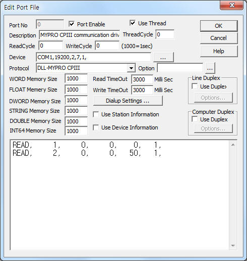
<Figure 1> is read setting example of MYPRO CPIII communication driver.
 |
| <Figure 1> Read setting example of MYPRO CPIII communication driver |
Device part of <Figure 1> input Com Port(COM1), Baud Rate(19200), Parity Bit(2), Data Bit(7), Stop Bit(1) respectively, according to setting of controller.
Note) Baud rate, parity bit, data bit, stop bit of MYPRO CPIII/MDC can set by using front panel's setting button.
MYPRO CPIII communication driver read schedule
Read schedule setting parameters are as follows:
1) Station – 1 ~ 31 station number. ( don't use 0 station number )
2) Read command – don't care.
3) Read start address – don't care.
4) Save start address for Communication Server – Saving start address of Communication Server.
5) Read size – fixed to 1. ( refer to <Table 1 > )
Read schedule example)
READ, 1, 0, 0, 0, 1,
READ, 2, 0, 0, 50, 1,
<Table 1> is data saving address and contents of MYPRO CPIII communication driver.
<Table 2> is data value and meanings for operation mode. <Table 3> is contacts and contents for each bit.
<Table 4> is name and alarm contents for each bit.
Data saving address |
Contnets |
Remarks |
Start addr + 0 ~ 15 |
current value of analog input 1 ~ 16 |
|
Start addr + 16 ~ 23 |
calculation value 1 ~ 8 |
|
Start addr + 24 ~ 29 |
setting value 1 ~ 6 |
|
Start addr + 30 |
operation mode |
refer to <Table 2> |
Start addr + 31 ~ 32 |
status of 32 bit input, output contact |
refer to <Table 3> |
Start addr + 33 ~ 34 |
alarm status 32 bit |
refer to <Table 4> |
| <Table 1> Data saving address and contents of MYPRO CPIII communication driver | ||
Operation mode |
Serial communication mode ( hex-decimal ) |
|
Off |
On |
|
manual |
10 |
15 |
automatic |
20 |
25 |
remote |
30 |
35 |
remote.automatic |
40 |
45 |
| <Table 2> Data value and meanings for operation mode | ||
Bit positon |
Contacts |
Contents |
b0 |
D/O-01 |
freezer (1/ 2) |
b1 ~ b3 |
D/O-02 ~ D/O-04 |
capacity control solenoid valve 1/3 ~ 3/3 for freezer (1/ 2) |
b4 |
D/O-05 |
irrigation solenoid valve |
b5 |
D/O-06 |
YOSAKU expansion valve (1/3) |
b6 |
D/O-07 |
auxiliary machinery |
b7 |
D/O-08 |
middle irrigation solenoid valve of freezer (1/2) |
b8 |
D/O-09 |
batch alarm |
b9 |
D/I-01 |
emergency stop |
b10 |
D/I-02 |
cooling water pressure rising switch |
b11 |
D/I-03 |
brine/cold water pressure rising switch |
b12 |
D/I-04 |
motor winding temperature rising switch of freezer (1/2) |
b13 |
D/I-05 |
operation(run) confirm of freezer (1/2) |
b14 |
D/I-06 |
external operation command |
b15 |
D/I-07 |
iInterlock |
b16 |
D/O-10 |
freezer 2/2 |
b17 ~ b19 |
D/O-11 ~ D/O-13 |
capacity control solenoid valve 1/3 ~ 3/3 for freezer 2/ 2 |
b20 |
D/O-14 |
YOSAKU expansion valve (2/3) |
b21 |
D/O-15 |
YOSAKU expansion valve (3/3) |
b22 |
D/O-16 |
don't use |
b23 |
D/O-17 |
middle irrigation solenoid valve of freezer (2/2) |
b24 ~ b27 |
DI/O |
don't use |
b28 |
D/I-08 |
motor winding temperature rising switch of freezer 2/2 |
b29 |
D/I-09 |
operation(run) confirm of freezer 2/2 |
b30 |
D/I-10 |
operation command of external freezer for 1 unit |
b31 |
D/I-11 |
external setting switching command |
| <Table 3> Contacts and contents for each bit | ||
Bit positon |
Name |
Contents |
b0 |
C1HDP |
discharge pressure rising switch shutdown alarm of freezer (1/2) |
b1 |
C1LOP |
irrigation, differential pressure lowering shutdown alarm of freezer (1/2) |
b2 |
C1HDT |
discharge temperature rising switch shutdown alarm of freezer (1/2) |
b3 |
C1HMA |
motor over-current shutdown alarm of freezer (1/2) |
b4 |
C1 SF |
operation shutdown alarm of freezer (1/2) |
b5 |
C1HMT |
motor winding temperature rising shutdown alarm of freezer (1/2) |
b6 |
C1HIP |
middle pressure rising shutdown alarm of freezer (1/2) |
b7 |
C1HOT |
irrigation temperature rising shutdown alarm of freezer (1/2) |
b8 |
C2HDP |
discharge pressure rising switch shutdown alarm of freezer 2/2 |
b9 |
C2LOP |
irrigation, differential pressure lowering shutdown alarm of freezer 2/2 |
b10 |
C2HDT |
discharge temperature rising switch shutdown alarm of freezer 2/2 |
b11 |
C2HMA |
motor over-current shutdown alarm of freezer 2/2 |
b12 |
C2 SF |
operation shutdown alarm of freezer 2/ 2 |
b13 |
C2HMT |
motor winding temperature rising shutdown alarm of freezer 2/2 |
b14 |
C2HIP |
middle pressure rising shutdown alarm of freezer 2/2 |
b15 |
C2HOT |
irrigation temperature rising shutdown alarm of freezer 2/2 |
b16 |
L CWP |
cooling water pressure lowering shutdown alarm |
b17 |
L BCP |
brine/cold water pressure lowering shutdown alarm |
b18 |
L COT |
brine/cold water temperature lowering shutdown alarm |
b19 |
LSUCP |
inhalation pressure lowering shutdown alarm |
b20 |
EMR |
emergency stop shutdown alarm |
b21 |
INTLK |
iInterlock shutdown alarm |
b22 ~ b23 |
|
don't use, |
b24 |
H COT |
brine/cold water temperature rising pre-alarm |
b25 |
L SSH |
inhalation overheated steam lowering pre-alarm |
b26 |
LISH |
middle overheated steam pre-alarm |
b27 ~ b31 |
|
don't use |
| <Table 4> Name and alarm contents for each bit | ||
MYPRO CPIII communication driver store the same data in WORD, DWORD, FLOAT, STRING memory, but the data format are different.
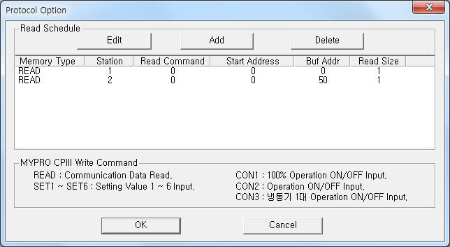
If you click the icon ![]() in protocol option part at
<Figure 1>, you
can see the dialog box such as <Figure 2>. you can also set read schedule by
using this part.
in protocol option part at
<Figure 1>, you
can see the dialog box such as <Figure 2>. you can also set read schedule by
using this part.
 |
| <Figure 2> Example of MYPRO CPIII communication driverí»s Option dialog box |
You can set read schedule by using ![]() ,
, ![]() ,
, ![]() button and listbox of <Figure
2>.
button and listbox of <Figure
2>.
 |
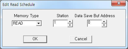
| <Figure 3> Example of MYPRO CPIII communication driverí»s read schedule Add/Edit dialog box |
When you click Add button or Edit button in dialogue box of <Figure 2>, dialogue box of <Figure 3> is shown.
You can set MYPRO CPIII/MDC controller by using 'write settings'.
Digital Write
Digital write and analog write have the same setting parameters except output value.
Analog Write
Analog write setting parameters are as follows:
1) PORT Port no. (0 ~ 255)
2) STATION 1 ~ 31 station number. ( don't use 0 station number )
3) ADDRESS data saving start address when READ write command. ( refer to <Table 1> )
4) Extra1 writing command = READ, SET1 ~ SET6, CON1 ~ CON3. ( refer to <Table 5> )
5) Extra2 don't care.
<Table 5> is write command and contents of MYPRO CPIII communication driver.
Write command |
Contents |
READ |
read command ( refer to <Table 1> ) |
SET1 ~ SET6 |
setting command for setting value 1 ~ 6 |
CON1 |
operation command of 100 % |
CON2 |
operation command |
CON3 |
run command for freezer 1 unit |
| <Table 5> Write command and contents of MYPRO CPIII communication driver | |
Write example 1)
PORT:0, station:1, ADDRESS:0100, Extra1: READ, Extra2 : 0
The setting parameter shown above is read request setting example of station 1 MYPRO CPIII controller.
After reading, the readed data save at 100 ~ 134 address WORD, DWORD, FLOAT memory such as <Table 1>.
Write example 2)
PORT:0, station:1, ADDRESS:0000, Extra1: SET1, Extra2 : 0
The setting parameter shown above is setting example for setting value 1.
Write example 3)
PORT:0, station:2, ADDRESS:0000, Extra1: SET6, Extra2 : 0
The setting parameter shown above is setting example for setting value 6.
Write example 4)
PORT:0, station:1, ADDRESS:0000, Extra1: CON1, Extra2 : 0
The setting parameter shown above is 100% operation command control( On or Off ) example of station 1 MYPRO CPIII controller.
Write example 5)
PORT:0, station:2, ADDRESS:0000, Extra1: CON1, Extra2 : 0
The setting parameter shown above is 100% operation command control( On or Off ) example of station 2 MYPRO CPIII controller.
Write example 6)
PORT:0, station:1, ADDRESS:0000, Extra1: CON3, Extra2 : 0
The setting parameter shown above is run command for freezer 1 unit control( On or Off ) example of station 1 MYPRO CPIII controller.
Please connect RS-485 communication cable to A( + ), B( - ) connector of MYPRO CPIII/MDC controller such as <Figure 4>.
RS-485 of computer MYPRO-CPIII/MDC controller
Tx+, Rx+ -------------------------------------- A connector
Tx-, Rx- -------------------------------------- B connector
<Figure 4> is appearance of MYPRO CPIII/MDC controller.
 |
| <Figure 4> Appearance of MYPRO CPIII/MDC controller |