MK Electronics DT Series communication driver is the driver to communicate with digital panel meter(DPM), automatic power factor corrector of MK Electronics in Korea.
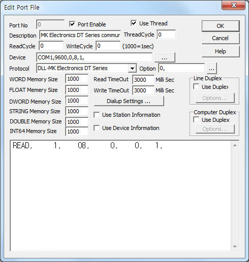
<Figure 1> is read setting example of MK Electronics DT Series communication driver.
 |
| <Figure 1> Read setting example of MK Electronics DT Series communication driver |
Device part of <Figure 1> input Com Port(COM1), Baud Rate(9600), Parity Bit(0), Data Bit(8), Stop Bit(1) respectively, according to setting of controller.
Also you can set 'mode of DT series'( 0 : Master, 1 : Slave, default = 0) by using option part.
MK Electronics DT Series communication driver read schedule
Read schedule setting parameters are as follows:
1) Station – 1 ~ 255 station number.
2) Read command – fixed to 08.
3) Read start address – don't care.
4) Save start address for Communication Server – Saving start address of Communication Server.
5) Read Size – fixed to 1.
Read schedule example)
READ, 1, 08, 0, 0, 1,
MK Electronics DT Series communication driver store the same data in WORD, DWORD, FLOAT memory, but the data format are different.
If you click the icon ![]() in protocol option part at
<Figure 1>, you
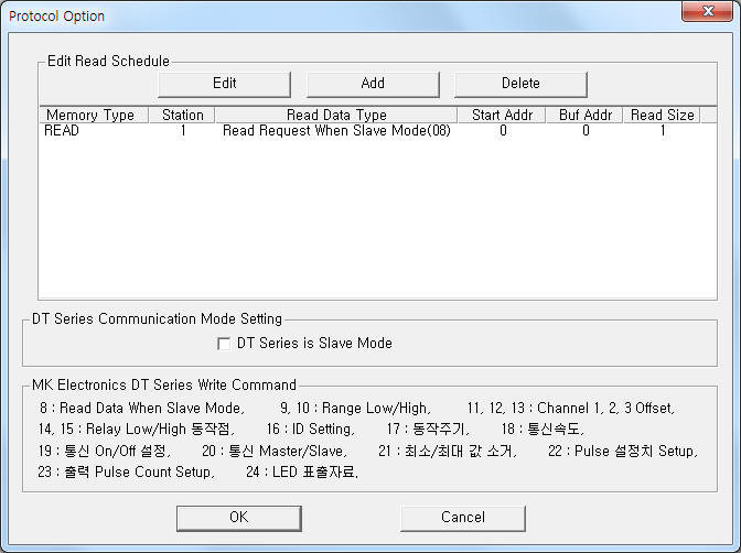
can see the dialogue box such as <Figure 2>. you can also set read schedule by
using this part.
in protocol option part at
<Figure 1>, you
can see the dialogue box such as <Figure 2>. you can also set read schedule by
using this part.
 |
| <Figure 2> Example of MK Electronics DT Series communication driverí»s Option dialog box |
You can set read schedule by using ![]() ,
, ![]() ,
, ![]() button and listbox of <Figure
2>.
button and listbox of <Figure
2>.
Also, you can set set mode of DT series by using the part of 'DT Series Slave Mode' shown in <Figure 2>.
 |
| <Figure 3> Example of MK Electronics DT Series communication driverí»s read schedule Add/Edit dialog box |
When you click Add button or Edit button in dialogue box of <Figure 2>, dialogue box of <Figure 3> is shown.
You can read and write by using 'write settings'.
Digital Write
Digital write and analog write have the same setting parameters except output value.
Analog Write
Analog write setting parameters are as follows:
1) PORT Port no. (0 ~ 255)
2) STATION 1 ~ 255 station number.
3) ADDRESS data saving start address when 08 read command.
4) Extra1 read/write command = 08, 09, 10, 11, 12, 13, 14, 15, 16, 17, 18, 19, 20, 21, 22, 23, 24. ( refer to <Table 1> )
5) Extra2 decimal point, 1 ~ 5 = 1 ~ 5 decimal point, 0 = don't use decimal point.
<table 1> is read/write command and contents of MK Electronics DT Series communication driver.
Command |
Contents |
Remarks |
08 |
read command when Slave mode |
|
09, 10 |
setting of Display Range low/high value |
|
11, 12, 13 |
setting of Channel 1/2/3 Offset |
|
14, 15 |
setting of Relay low/high operation point |
|
16 |
setting of ID |
1 ~ 255 |
17 |
setting of operation period |
0 ~ 99 |
18 |
setting of baud rate |
9600/4800/2400 |
19 |
retting of communication ON/OFF |
1 : ON, 0 : OFF |
20 |
setting of communication Master/Slave |
1 : Master, 0 : Slave |
21 |
delete of low/high value |
1 : don't delete, 0 : delete |
22 |
Pulse setting value |
|
23 |
output Pulse Count Setup |
|
24 |
LED display data |
|
| <table 1> Read/write command and contents of MK Electronics DT Series communication driver | ||
Write example 1)
PORT:0, station:1, ADDRESS:0020, Extra1: 08, Extra2 : 0
The setting parameter shown above is read request command example of station 1 MK DT SERIES controller.
After reading, the readed data save at 20 WORD, DWORD, FLOAT memory.
Connection of main power and communication cable are as follows:
Connection of main power
Please connect 220V AC or 110V AC main power to 9, 10 connector of MK Electronics DT Series controller such as <Figure 4>.
 |
| <Figure 4> Connection example of main power and communication cable to MK Electronics DT Series controller |
Connection of communication cable
Please connect RS-485 communication cable to 7 ( + ), 8( - ) connector.
RS-485 of computer MT Series
+ ----------------------------------- 7( + ) connector
- ----------------------------------- 8( - ) connector
<Figure 5> is appearance of MK Electronics DT Series controller.
 |
| <Figure 5> Appearance of MK Electronics DT Series controller |
MK DT Series controller can set station, baud rate, ... by using setting button of front panel. ( refer to <Figure 5> )
1) Press Mode -> Set -> Mode button. Then, will be entered to setting mode.
2) Press 'SET' button. Then will be displayed 'Id-SE' at screen.
3) Select station number by using 'Right', 'Up' button and press 'SET' button.
4) Please press 'MODE' button several times. Then will be displayed 'b9600' at screen.
5) Select baud rate among 2400, 4800, 9600 by using 'Right', 'Up' button and press 'SET' button.
6) Please return to operation mode by pressing 'SET' button.