MKS 146 Vacuum Gauge Measurement communication driver is the driver to communicate with type 146 series controller of MKS Instruments, Inc. in U.S.A.
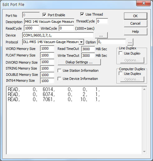
<Figure 1> is read setting example of MKS 146 Vacuum Gauge Measurement communication driver.
 |
| <Figure 1> Read setting example of MKS 146 Vacuum Gauge Measurement communication driver |
Device part of <Figure 1> input Com Port(COM1), Baud Rate(9600), Parity Bit(2), Data Bit(7), Stop Bit(1) respectively, according to setting of controller.
Also you can set 'use of BCC check'( 0 : don't use, 1 : use, default = 0) by using option part.
Note) Baud rate(300 ~ 9600), parity bit(0, 1, 2), data bit(7, 8) of MKS TYPE 146 controller can set by front panel button.
MKS 146 Vacuum Gauge Measurement communication driver read schedule
Read schedule setting parameters are as follows:
1) Station – don't care.
2) Read command – command and channel = 601x, 602x, 603x, 604x, 605x, 606x, 6071, 608x, 6091, 60A*, 60B*, 60C1, 60D1, 60E1, 60F1, 7011, 7021, 7031, 7041, 7051, 7061.
( x : 1, 2, 3, 4, 5, 6 = channel number, * : A, B, C, D = Parameter, refer to <Table 1> )
3) Read start address – don't care.
4) Save start address for Communication Server – Saving start address of Communication Server.
5) Read size – fixed to 1.
Read schedule example)
READ, 0, 6014, 0, 0, 1,
READ, 0, 6074, 0, 2, 1,
READ, 0, 7061, 0, 10, 1,
<Table 1> is read command and contents of MKS 146 Vacuum Gauge Measurement communication driver.
| Read command | Contents | Data saving address and contnets | Remarks |
| 601x | Channel Pressure | Start addr + 0 : pressure value | X = 1 ~ 6 channel number |
| 602x | Channel Pressure with Time Stamp | Start addr + 0 : readed time, (10 mSec unit) Start addr + 1 : pressure value |
|
| 603x | Channel Voltage | Start addr + 0 : voltage value | |
| 604x | Ion Current | Start addr + 0 : Ion current value | |
| 605x | Emission Current | Start addr + 0 : Emission current value | |
| 606x | Pressure Leak Rate | Start addr + 0 : Leak Rate value | |
| 6071 | Analog Set Point | Start addr + 0 : Analog Set Point value | last character of command = 1 or , other |
| 608x | Channel Condition | Start addr + 0 : channel status value ( 0=ON, 1=Low Power Defas, 2=Underranged, 3=Overranged, 4=Manually Off, 5=Auto Off, 6=High Power Degas, 7=Initializing, 8=Zeroing, 9=Bad Sensor, 10=DisConnected, 11=Channel Not Installed ), Start addr + 1 : pressure value( only status value = 0 ) |
X = 1 ~ 6 channel number |
| 6091 | Power Up Status | Start addr + 0 : status( refer to <Table 2> ) | last character of command = 1 or , other |
| 60A* | Relay Status | Start addr + 0 :
Parameter, (0 ~ 3 = A ~ D) Start addr + 1 : status value, (4 = Enabled, 3 = Disabled, 19 = Trip) |
X = A, B, C, D Parameter |
| 60B* | Alarm Status | ||
| 60C1 | Current Control Mode | Start addr + 0 :
Over status, ( 0 = No Over, 1 = Override Enabled ) Start addr + 1 : Mode ( 0 = Auto, 2 = Close, 7 = Hold, 12 = Manual, 14 = Open ) |
last character of command = 1 or , other |
| 60D1 | Current Recipe | Start addr + 0 :
Over status, ( 0 = No Over, 1 = Override Enabled ) Start addr + 1 : Recipe ( 1 ~ 4 Recipe) |
|
| 60E1 | Current PID Set Point | Start addr + 0 :
Type, ( 0 = Analog, 1 = Digitial) Start addr + 1 : Set Point value |
|
| 60F1 | PCS Output | Start addr + 0 : PCS Output value | |
| 7011 | Software Version | Start addr + 0 : Software Version value | |
| 7021 | Channel Status | Start addr + 0 ~ 3 : channel 1 ~ 4 status, save string data at STRING
memory. (0=ON, 1=OFF, 2=AOFF, 3=DCNT, 4=OVER, 5=UNDR, 6=INIT, 6=ZERO, 8=E1, 9=----) |
|
| 7031 | Alarm Status | Start addr + 0 ~ 3 :
A ~ D Alarm status, save string at STRING memory. (0=ENAB, 1=ENAL, 2=ENLT, 3=DSBL, 4=----) |
|
| 7041 | Configuration Setup | Start addr + 0 ~ 4 :
1 ~ 5 Slot status, save string at STRING memory. (0=CC, 1=CLN, 2=C107, 3=C120, 4=CNCN, 5=PRCN, 6=C-, 7=CN--, 8=CNPR, 9=CNTL, 10=AUXO, 11=----, 12=PR--, 13=PRPR, 14=MFC, 15=HCL, 16=HCH, 17=1A) |
|
| 7051 | Rear Panel Status | Start addr + 0~3 :
Remote Zero 1~4 channel status, Start addr + 4~7 : Latch Relay A~D status, Start addr + 8 : Front Panel Lockout status, Start addr + 9 : Open value status, Start addr + 10 : Manual value Control status, Start addr + 11 : Close status, Start addr + 12~14 : Set Point B~D status, save string at STRING memory. ( 0=Low(ground), 1=High(5Volts), 2=other) |
|
| 7061 | Reference Voltage | Start addr + 0~4 : 5 Calibration number value. | |
| <Table 1> Read command and contents of MKS 146 Vacuum Gauge Measurement communication driver | |||
| Bit position | Value(hex-decimal) |
Error status |
| ¸ğµç ºñÆ® OFF | 00 |
No Errors |
| 0 | 01 |
Bad Factory Calibration |
| 1 | 02 |
Bad User Calibration |
| 2 | 04 |
Bad Zero Calibration |
| 3 | 08 |
New Configuration |
| 4 | 10 |
Bad ROM |
| 5 | 20 |
Bad RAM |
| 6 | 40 |
Reserved |
| 7 | 80 |
|
| <Table 2> Error status for each bit of Power Up Status(6091) read command | ||
MKS 146 Vacuum Gauge Measurement communication driver store the same data in WORD, DWORD, FLOAT, STRING( for related command ) memory, but the data format are different.
If you click the icon ![]() in protocol option part at
<Figure 1>, you
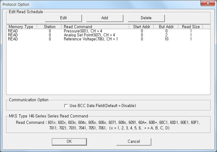
can see the dialog box such as <Figure 2>. you can also set read schedule by
using this part.
in protocol option part at
<Figure 1>, you
can see the dialog box such as <Figure 2>. you can also set read schedule by
using this part.
 |
| <Figure 2> Example of MKS 146 Vacuum Gauge Measurement communication driver¡¯s Option dialog box |
You can set read schedule by using ![]() ,
, ![]() ,
, ![]() button and listbox of <Figure
2>.
button and listbox of <Figure
2>.
Also, you can set use of BCC check by using the part of 'Use BCC Data Filed' shown in <Figure 2>.
 |
| <Figure 3> Example of MKS 146 Vacuum Gauge Measurement communication driver¡¯s read schedule Add/Edit dialog box |
When you click Add button or Edit button in dialogue box of <Figure 2>, dialogue box of <Figure 3> is shown.
You can set MKS 146 Vacuum Gauge Measurement by using 'write settings'.
Digital Write
Digital write setting parameters are as follows:
1) PORT Port no. (0 ~ 255)
2) STATION don't care.
3) ADDRESS don't care.
4) Extra1 writing command and element, refer to <Table 3>. ( don't input 1st @ character, last CR and BCC )
5) Extra2 don't care.
<Table 3> is write command and element of MKS 146 Vacuum Gauge Measurement communication driver.


<Table 3> Write command and element of MKS 146 Vacuum Gauge Measurement communication driver
Write example 1)
PORT:0, station:1, ADDRESS:0000, Extra1: 0812:ON, Extra2 : 0
The setting parameter shown above is Channel Power ON of no. 2 setting example.
Write example 2)
PORT:0, station:1, ADDRESS:0000, Extra1: 0812:OFF, Extra2 : 0
The setting parameter shown above is Channel Power OFF of no. 2 setting example.
Analog Write
Analog write and digital write have the same setting parameters except output value.
Connection of communication cable and main power are as follows:
Connection of communication cable
Please connect direct RS-232C communication cable to 9 pin connector of MKS TYPE 146 controller.
<Figure 4> is connection example of main power and communication cable to MKS TYPE 146 controller.
Note) 9pin connector of MKS TYPE 146 controller use direct RS-232C communication cable.
<Figure 5> is appearance of MKS TYPE 146 controller.
 |
| <Figure 4> Connection example of main power and communication cable to MKS TYPE 146 controller |
 |
| <Figure 5> Appearance of MKS TYPE 146 controller |
Connection of main power
Please connect 220V AC( or 110V ) AC main power to power input connector such as <Figure 4>.
Note) Check main power input type, 230V or 110V selection switch.
MKS TYPE 146 controller can set baud rate by using setting button of front panel. ( refer to <Figure 5> )
1) Please ¡®DISPLAY MODE¡¯ button several times and enter to ¡®SETUP¡¯ mode.
2) Press 'Up', 'Down' button several times when blinking the left, up side number.
3) Press '5' button. Then will be displayed '9600' (or other character ).
4) Press ¡®ENTER¡¯ button. Then, will be blink 'the number'.
5) Please select baud rate(300, 1200, 2400, 4800, 9600) by pressing 'Up', 'Down' button.
6) Press 'ENTER' button. Then will be displayed ¡®146¡¯( or DL) character.
7) Select protocol type to '146' and press 'ENTER' button. Then will be displayed ¡®7E¡¯, ....
8) Select 'data bit' by pressing '7' or '8' button. Select 'parity bit'( EVEN/ODD/NONE ) by using 'Up', 'Down' button.
9) Complete setting by pressing ¡®DISPLAY MODE¡¯ button.