MESL-S New Toshiba Light communication driver is the driver to communicate with lighting controller of Toshiba in Japan.
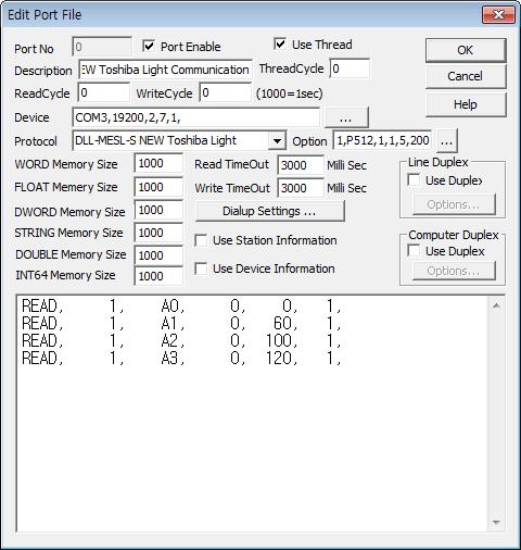
<Figure 1> is read setting example of MESL-S New Toshiba Light communication driver.
 |
| <Figure 1> Read setting example of MESL-S New Toshiba Light communication driver |
Device part of <Figure 1> input Com Port(COM3), Baud Rate(19200), Parity Bit(2), Data Bit(7), Stop Bit(1) respectively, according to setting of controller.
Baud rate of MESL-S controller can set in 1200, 2400, 4800, 9600, 19200.
Also you can set 'bit unit data( A0, A1, A3, C0 ~ C3, E0 ) saving method'( 0 : hex-decimal, 1 : decimal, default = 0), model of controller(P256 : 256 point model, P512 : 512 point module, default = P256), save other response( 0 = don't save, 1 = save, default = 0), weather to use Polling data read(0 = don't use, 1 = use, default = 0), interval of each read schedule when using 'Polling data read'(0 ~ 255, default = 5 second), read timeout of Polling data read(50 ~ 2000, default = 200 mSec), waiting time after write(0 ~ 1000, default = 300 mSec) by using option part. Each argument is a comma-delimited.
Note) When you set 'decimal(10 bit)' unit data saving method, communication driver save from 1 (2nd) bit of start data saving address. ( 1st saving address = only save 9 bit )
MESL-S New Toshiba Light communication driver read schedule
Read schedule setting parameters are as follows:
1) Station – 1 ~ 31 station number.
2) Read data type – data type = A0, A1, A2, A3, A4, C0, C1, C2, C3, E0. ( refer to <Table 1> )
3) Read start address – don't care.
4) Save start address for Communication Server – Saving start address of Communication Server.
5) Read Size – fixed to 1.
Read schedule example)
READ, 1, A0,
0, 0, 1,
READ,
1, A1, 0,
60, 1,
READ, 1,
A2, 0, 100,
1,
READ, 1, A3,
0, 120, 1,
MESL-S New controller have 1024(64 word, or 256, 512) indivisual and group status value.
Note) A0, A1, A3, C0 ~ C4 read data type save 1 bit data at each data saving address.
<Table 1> is read data type and contents of MESL-NEW Toshiba Light communication driver.
| Read data type | Contents | Saving data |
16Bit/10Bit |
| A0 | read of total indivisual point | 1 bit data each saving address OFF = 0, ON = 1 |
enable |
| A1 | read of total group switch data | ||
| A2 | read of total Zone/Pattern | 2 bit data each saving address off : 00, on : 01, photosensitive 1 : 10, photosensitive 2 : 11 |
always hex-decimal data saving |
| A3 | read of total monitoring controller | 1 bit data each saving address OFF = 0, ON = 1 |
enable |
| A4 | read of total illumination circuit | 0 ~ 100 illumination value 0~100 |
word |
| C0 | read of total optical sensor operation 1 column | 1 bit data each saving address OFF = don't operation, ON = operation |
enable |
| C1 | read of total optical sensor operation 2 column | ||
| C2 | read of total optical sensor operation 3 column | ||
| C3 | read of optical sensor representation 1 ~ 3 column | ||
| E0 | read of total system, device error | 1 bit data each saving address OFF = return(normal), ON = error |
|
| <Table 1> Read data type and contents of MESL-NEW Toshiba Light communication driver | |||
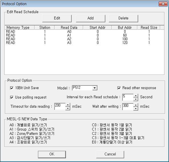
If you click the icon ![]() in protocol option part at
<Figure 1>, you
can see the dialogue box such as <Figure 2>. you can also set read schedule by
using this part.
in protocol option part at
<Figure 1>, you
can see the dialogue box such as <Figure 2>. you can also set read schedule by
using this part.
 |
| <Figure 2> Example of MESL-S New Toshiba Light communication driver¡¯s Option dialog box |
You can set read schedule by using ![]() ,
, ![]() ,
, ![]() button and listbox of <Figure
2>.
button and listbox of <Figure
2>.
Also, you can set set bit unit data saving method, model of controller, Read other response, Use polling request, Interval for each read schedule, Timeout for data reading and wait after writing by using the part of '10Bit Unit Save', 'Model', 'Read other response', 'Use polling request', 'Interval for each Read schedule', 'Timeout for data reading', 'Wait after writing' shown in <Figure 2>.
 |
| <Figure 3> Example of MESL-S New Toshiba Light communication driver¡¯s read schedule Add/Edit dialog box |
When you click Add button or Edit button in dialogue box of <Figure 2>, dialogue box of <Figure 3> is shown.
You can control MESL-S controller by using 'write settings'.
Digital Write
Digital write setting parameters are as follows:
1) PORT Port no. (0 ~ 255)
2) STATION 1 ~ 31 station number.
3) ADDRESS 0001 ~ 1024 writing address for indivisual, group point control.
4) Extra1 writing data type.
A0 : indivisual point,
A1 : group point,
A2 : Zone/Pattern point,
A3 : monitoring controller,
A4 : illumination circuit.
5) Extra2 photosensitive 1, 2 selection when A2 writing data type.
Write example 1)
PORT:0, station:1, ADDRESS:0005, Extra1: A0, Extra2 : 0
The setting parameter shown above is 5 address indivisual point control example of 1 station MESL-S.
Write example 2)
PORT:0, station:1, ADDRESS:0007, Extra1: A1, Extra2 : 0
The setting parameter shown above is 7 address group point control example of 1 station MESL-S.
Write example 3)
PORT:0, station:1, ADDRESS:0003, Extra1: A2, Extra2 : 0
The setting parameter shown above is 3 address Zone/Pattern control(On/Off) example of 1 station MESL-S.
Write example 4)
PORT:0, station:2, ADDRESS:0003, Extra1: A2, Extra2 : 1
The setting parameter shown above is 3 address Zone/Pattern control( photosensitive 1, 2) example of 2 station MESL-S.
Analog Write
Analog write setting parameters are as follows:
1) PORT Port no. (0 ~ 255)
2) STATION 1 ~ 31 station number.
3) ADDRESS 0001 ~ 1024 writing address for indivisual, group point control.
4) Extra1 writing data type.
A0 : indivisual point,
A1 : group point,
A2 : Zone/Pattern point,
A3 : monitoring controller,
A4 : illumination circuit.
5) Extra2 photosensitive 1, 2 selection when A2 writing data type.
Write example 1)
PORT:0, station:1, ADDRESS:0001, Extra1: A4, Extra2 : 0
The setting parameter shown above is 1 address illumination setting( 0 ~ 100 % ) example of 1 station MESL-S.
Please connect RS-485/422 communication cable to T+, T-, R+, R- connector of MESL-S controller such as <Figure 4>, <Figure 5>.
<Figure 4> is connection example of communication cable and pain power to MESL-S controller.
 |
| <Figure 4> Connection example of communication cable and pain power to MESL-S controller |
MESL-S controller RS-485/422 connector of computer
T+ ----------------------------------- R+
T- ----------------------------------- R-
R+ ----------------------------------- T+
R- ----------------------------------- T-
<Figure 5> Connection diagram of RS-485/422 communication cable between MESL-S and computer