Mentor II communication driver is the driver to communicate with DC driver controller of Control Techniques.
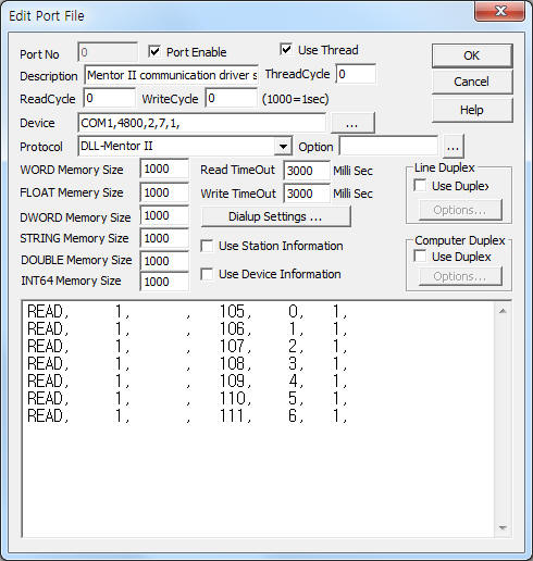
<Figure 1> is read setting example of Mentor II communication driver.
 |
| <Figure 1> Read setting example of Mentor II communication driver |
Device part of <Figure 1> input Com Port(COM1), Baud Rate(4800), Parity Bit(2), Data Bit(7), Stop Bit(1) respectively, according to setting of controller.
Note) Baud rate can set parameter 11.11 of Mentor II controller. (parameter 11.11 : 0 = 4800bps )
Mentor II communication driver read schedule
Read schedule setting parameters are as follows:
1) Station – station number. ( value of parameter 11.12 )
2) Read data type – don't care.
3) Read start address – reading paramter number. ex) 10.01 -> 1001
4) Save start address for Communication Server – Saving start address of Communication Server.
5) Read Size – fixed to 1.
Read schedule example)
READ, 1, , 105, 0, 1,
READ, 1, , 106, 1, 1,
READ, 1, , 107, 2, 1,
READ, 1, , 108, 3, 1,
READ, 1, , 109, 4, 1,
READ, 1, , 110, 5, 1,
READ, 1, , 111, 6, 1,
You can set Mentor II controller by using 'writing settings'.
Digital Write
Digital write setting parameters are as follows:
1) PORT Port no. (0 ~ 255)
2) STATION station number. ( value of parameter 11.12 )
3) ADDRESS writing parameter address. ex) 10.02 -> 1002, 1.13 -> 113
4) Extra1 don't care.
5) Extra2 don't care.
Write example 1)
PORT:0, station:1, ADDRESS:1002, Extra1: , Extra2 : 0
The setting parameter shown above is forward direction speed setting example of 1 station Mentor II controller.
Analog Write
Analog write setting parameters are as follows:
1) PORT Port no. (0 ~ 255)
2) STATION station number. ( value of parameter 11.12 )
3) ADDRESS writing parameter address. ex) 1.05 -> 105
4) Extra1 don't care.
5) Extra2 don't care.
Write example 1)
PORT:0, station:1, ADDRESS:0106, Extra1: , Extra2 : 0
The setting parameter shown above is maximum speed of forward direction setting example.
Please connect RS-485 communication cable to PL2 socket of Mentor II controller. ( you can select 2 Wire or 4 Wire connection, according to setting of 11.13 Parameter )
<Figure 2> is diagram of RS-485 communication cable for 4 Wire connection.
 |
| <Figure 2> Diagram of RS-485 communication cable for 4 Wire connection |
Menter II Driver controller read or write by using Parameter value.
<Table 1> is part of Parameter address and contents.
Please refer to manual of Mentor II controller for more Parameter address and contents.
| Parameter address | Contents | Range | Type | Default |
| 01.01 | Pre-offset speed reference | 1000 | Read Only | |
| 01.02 | Post-offset speed refrence | 1000 | Read Only | |
| 01.03 | Pre-ramp refrence | 1000 | Read Only | |
| 01.04 | Offset | 1000 | Read/Write | +000 |
| 01.05 | Inch reference | 1000 | Read/Write | +050 |
| 01.06 | maximum speed(forward) | 0~+1000 | Read/Write | +1000 |
| 01.07 | minimum speed(forward) | 0~+1000 | Read/Write | +000 |
| 01.08 | minimum speed(reverse) | -1000~0 | Read/Write | +1000 |
| 01.09 | (4Q) maximum speed(reverse)(1Q) | -1000~0-1000~0 | Read/WriteRead/Write | -1000+000 |
| 01.10 | (4Q)reference selector(1Q) | 0 or 10 or 1 | Read/Write Read/Write | 10 |
| 01.11 | reference 'ON' | 0 or 1 | Read/Write | 0 |
| 01.12 | reverse selector | 0 or 1 | Read/Write | 0 |
| 01.13 | Inch selector | 0 or 1 | Read/Write | 0 |
| <Table 1> Part of Parameter address and contents | ||||