MELSEC FX CPU communication driver is the driver to communicate with Melsec FX series's loader connector of Mitsubishi in Japan. ( FX-16MR, ... )
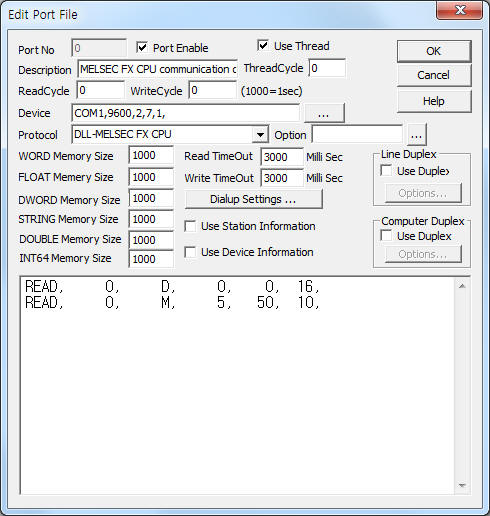
<Figure 1> is read setting example of MELSEC FX CPU communication driver.
 |
| <Figure 1> Read setting example of MELSEC FX CPU communication driver |
Device part of <Figure 1> input Com Port(COM1), Baud Rate(9600), Parity Bit(2), Data Bit(7), Stop Bit(1) respectively.
Note) Baud rate, parity bit, data bit, stop bir of FX series's loader port are fixed to 9600, 2, 7, 1. Also station is fixed to 0.
MELSEC FX CPU communication driver read schedule
Read schedule setting parameters are as follows:
1) Station – don't care. fixed to 0.
2) Read memory type – memory type = S, X, Y, Y, M, C, D, .... ( refer to <Table 1> )
S : Step Relay ( can set, 10 bit unit absolute address ),
X : Input Relay,
Y : Output Relay,
T : Timer,
M : Internal Relay,
C : Counter,
D : Data Register,
space, W, ... : word unit absolute address.
3) Read start address – reading start address in memory.
S, X, Y, M memory type : 10 bit unit decimal address
example 1) X memory type : 1 = X10 address,
example 2) Y memory type : 5 = Y50 address,
example 3) M memory type : 12 = M120 address,
example 4) M memory type : 25 = M250 address,
example 5) M memory type : 30 = M300 address
T, TF, C, CF, D, DF memory type : word unit decimal address.
4) Save start address for Communication Server – Saving start address of Communication Server.
5) Read Size – word/10 bit unit read size.
S, X, Y, M memory type : 10bit unit read size(1 ~ 50),
example 1) 1 = read of 10 bit data,
example 2) 5 = read of 50 bit data,
example 3) 50 = read of 500 bit data
T, TF, C, CF, D, DF memory type : word unit read size(1 ~ 32 word)
Read schedule example)
READ, 0, D, 0, 0, 16,
READ, 0, M, 5, 50, 10,
Note) S, X, Y, M memory type save 10 bit at each memory address of Communication Server, T, C, D memory type save word data at each memory address.
<Table 1> is memory type and contents of MELSEC FS series PLC( FX-16MR ).
| Memory type | Unit | Contents | Size(byte unit) | Range of read start address(word unit) | Remarks |
| S | bit | Step Relay | S0 ~ S999 | 0 ~ 499 | 10 bit unit reading start address/ read size |
| X | Input Relay | X0 ~ X127 | 0 ~ 63 | ||
| Y | Output Relay | Y0 ~ Y127 | 0 ~ 63 | ||
| M | Internal Relay | M0 ~ M1023 | 0 ~ 511 | ||
| T, TF | byte (word) |
Timer | T0 ~ T255 | 0 ~ 127 | word unit reading start address/ read size |
| C, CF | Counter | C0 ~ C255 | 0 ~ 127 | ||
| D, DF | Data Register | D0 ~ D2999 | 0 ~ 1499 | ||
| <Table 1> Memory type and contents of MELSEC FS series PLC ( FX-16MR ) | |||||
Note) If input space, W, ..., you can read or write by word unit absolute address. ( S memory type = 10 bit unit absolute address reading/writing )
If you click the icon ![]() in protocol option part at
<Figure 1>, you
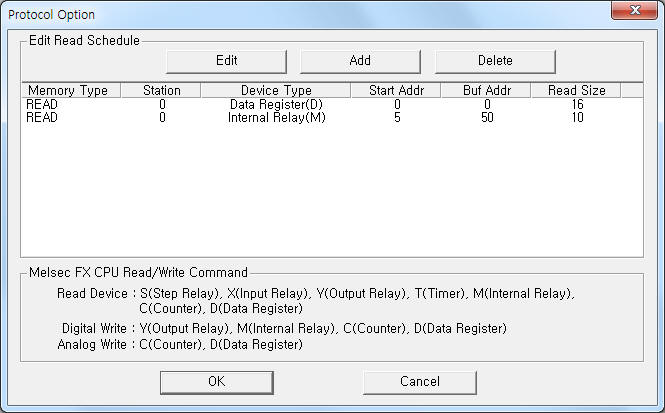
can see the dialogue box such as <Figure 2>. you can also set read schedule by
using this part.
in protocol option part at
<Figure 1>, you
can see the dialogue box such as <Figure 2>. you can also set read schedule by
using this part.
 |
| <Figure 2> Example of MELSEC FX CPU communication driverí»s Option dialog box |
You can set read schedule by using ![]() ,
, ![]() ,
, ![]() button and listbox of <Figure
2>.
button and listbox of <Figure
2>.
 |
| <Figure 3> Example of MELSEC FX CPU communication driverí»s read schedule Add/Edit dialog box |
When you click Add button or Edit button in dialogue box of <Figure 2>, dialogue box of <Figure 3> is shown.
You can set Melsec PLC by using 'writing settings'.
Digital Write
Digital write setting parameters are as follows:
1) PORT Port no. (0 ~ 255)
2) STATION don't care. fixed to 0.
3) ADDRESS writing address in PLC memory.( refer to <Table 1> )
Y, M memory type : decimal unit writing bit address,
C, D memory type : decimal unit writing word address.
4) Extra1 write memory type.
Y, M : bit writing,
C, D : bit writing after bit operation( word data ),
black, ... : bit unit writing by absolute address.
5) Extra2 bit position when C, D memory type.
C, D memory type : 0 ~ 15 writing bit position,
other : don't care.
Write example 1)
PORT:0, station:0, ADDRESS:0000, Extra1: Y, Extra2 : 0
The setting parameter shown above is bit control(On/Off) example for Y0 address ( bit unit ).
Write example 2)
PORT:0, station:0, ADDRESS:0005, Extra1: Y, Extra2 : 0
The setting parameter shown above is bit control(On/Off) example for Y5 address ( bit unit ).
Write example 3)
PORT:0, station:0, ADDRESS:0128, Extra1: M, Extra2 : 0
The setting parameter shown above is bit control(On/Off) example for M128 address ( bit unit ).
Write example 4)
PORT:0, station:0, ADDRESS:0012, Extra1: C, Extra2 : 2
The setting parameter shown above is bit control(On/Off) example for 2(3rd) bit of C12(C24 ~ C25 byte address) word address.
Write example 5)
PORT:0, station:0, ADDRESS:1124, Extra1: D, Extra2 : 15
The setting parameter shown above is bit control(On/Off) example for F(16th) bit of D1124(D2248 ~ D2249 byte address) word address.
Note) If input S memory type at Extar1, you can bit write by absolute address.
Analog Write
Analog write setting parameters are as follows:
1) PORT Port no. (0 ~ 255)
2) STATION don't care. fixed to 0.
3) ADDRESS decimal unit(word) writing address in PLC memory.( refer to <Table 1> )
4) Extra1 writing memory type.
C, D : word(byte) unit writing of C, D memory,
black, ... : word unit writing by absolute address.
5) Extra2 don't care.
Write example 1)
PORT:0, station:0, ADDRESS:0000, Extra1: C, Extra2 : 0
The setting parameter shown above is word write example for C0(C0 ~ C1 byte address) word address.
Write example 2)
PORT:0, station:0, ADDRESS:0030, Extra1: D, Extra2 : 0
The setting parameter shown above is word write example for D30(D60 ~ D61 byte address) word address.
Write example 3)
PORT:0, station:0, ADDRESS:0326, Extra1: D, Extra2 : 0
The setting parameter shown above is word write example for D326(D652 ~ D653 byte address) word address.
Note) If input W( or space, WF, ... ) memory type at Extar1, you can word write by absolute address.
Connection of communication cable and main power are as follows :
Connection fo communication cable
MELSEC FX CPU series normally support RS-422 communication. ( can use RS-232C connection according to CPU model)
Generally, you should to use RS-422 To RS-232C Converter (MITSUBISHI producr, ...), and connect direct RS-232C communication cable between computer and Convert.
<Figure 4> is connection example of communication cable and pain power at FX-16MR PLC.
 |
| <Figure 4> Connection example of communication cable and pain power at FX-16MR PLC |
Note) When you using RS-422 To RS-232C Converter of MITSUBISHI product, you should to connect direct RS-232C cable.
Connection of main power
Please connect 100 ~ 240 V AC main power to L, N connector such as <Figure 4>.