MCU100 Mark communication driver is the driver to communicate with marking controller of Jeil M Tech Co., Ltd. in Korea.
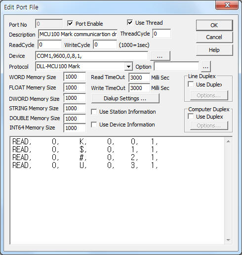
<Figure 1> is read setting example of MCU100 Mark communication driver.
 |
| <Figure 1> Read setting example of MCU100 Mark communication driver |
Device part of <Figure 1> input Com Port(COM1), Baud Rate(9600), Parity Bit(0), Data Bit(8), Stop Bit(1) respectively. ( fixed to 9600, 0, 8, 1 )
MCU100 Mark communication driver read schedule
Read schedule setting parameters are as follows:
1) Station – don't care.
2) Read command – command = G, H, I, J, K, L, M, O, P, R, S, U, $, #. ( refer to <Table 1> )
3) Read start address – don't care.
4) Save start address for Communication Server – Saving start address of Communication Server.
5) Read Size – fixed to 1.
Read schedule example)
READ, 0, K, 0, 0, 1,
READ, 0, $, 0, 1, 1,
READ, 0, #, 0, 2, 1,
READ, 0, U, 0, 3, 1,
<Table 1> is read command and contnents of MCU100 Mark communication driver.
| Read command | Contents | Rnage | Remarks |
| G | read of block type | 1 = linear(LN), 2 = circular(CR), 3 = Plot(PL), 4 = linear(CY) | |
| H | selection of font | 1 = standard 60% ming, 2 = standard 60% gothic, 3 = 5 X 7 Dot, 3 ~ 6 = user selection character |
|
| I | X block Offset | 0 ~ | X, Y axis conveyance distance, start point of marking |
| J | Y block Offset | ||
| M | character spacing | ||
| O | character height | ||
| Q | lot number | start point of serial number | |
| K | radius of the circular array | when circular marking | |
| L | marking start point of circular | ||
| P | marking direction | 0 = X+, 1 = X-, 2 = Y+, 3 = Y- | |
| R | setting of serial number | +9 ~ 0 ~ -9 | |
| S | setting of stop after marking | Y(use) = 1, N(don't use) = 0 | |
| U | marking data setting | number, character, ... 0 ~ 40 character per block( max : 999 block) | |
| $ | setting of mark up | 0 ~ 99999 | |
| # | Unit number | ||
| <Table 1> Read command and contnents of MCU100 Mark communication driver | |||
MCU100 Mark communication driver for MCC 2060 store the same data in WORD, DWORD, FLOAT memory, but the data format are different.
Also, save readed string to STRING memory.( for U, ... command )
If you click the icon ![]() in protocol option part at
<Figure 1>, you
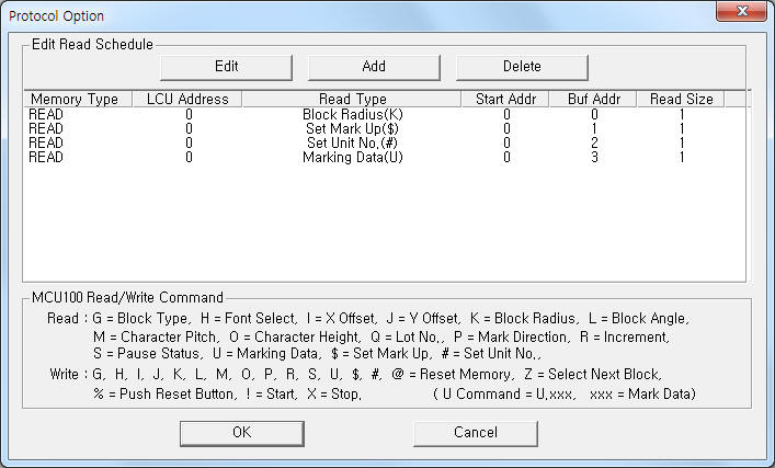
can see the dialogue box such as <Figure 2>. you can also set read schedule by
using this part.
in protocol option part at
<Figure 1>, you
can see the dialogue box such as <Figure 2>. you can also set read schedule by
using this part.
 |
| <Figure 2> Example of MCU100 Mark communication driver¡¯s Option dialog box |
You can set read schedule by using ![]() ,
, ![]() ,
, ![]() button and listbox of <Figure
2>.
button and listbox of <Figure
2>.
 |
| <Figure 3> Example of MCU100 Mark communication driver¡¯s read schedule Add/Edit dialog box |
When you click Add button or Edit button in dialogue box of <Figure 2>, dialogue box of <Figure 3> is shown.
You can set characters to be marked, start point, ... by using 'writing settings'.
Digital Write
Digital write and analog write have the same setting parameters except output value.
Analog Write
Analog write setting parameters are as follows:
1) PORT Port no. (0 ~ 255)
2) STATION don't care.
3) ADDRESS don't care.
4) Extra1 command = @, G, H, I, J, K, L, M, O, P, R, S, U, Z, $, #, %, !. ( refer to <Table 2> )
5) Extra2 marking data read option when U command.
0 = U.xxx, xxx : character to be marked,
1 = read marking character at 1st line data of ¡®work folder\SCAN\comm%03d.ini¡¯ file.
<Table 2> is write command contents of MCU100 Mark communication driver.
| Write command(Extra1) | Contents | Output value | Extra2 |
| @ | delete old data | don't care | don't care |
| G | setting of block type | 1 = linear(LN), 2 = circular(CR), 3 = Plot(PL), 4 = linear(CY) | |
| H | selection of font type | 1 = standard 60% ming, 2 = standard 60% gothic, 3 = 5 X 7 Dot, 3 ~ 6 = user selection character |
|
| I | X block Offset | 0 ~ | |
| J | Y block Offset | ||
| M | character spacing | ||
| O | character height | ||
| Q | lot number | ||
| K | radius of the circular array | ||
| L | marking start point of circular | ||
| P | marking direction | 0 = X+, 1 = X-, 2 = Y+, 3 = Y- | |
| R | setting of serial number | +9 ~ 0 ~ -9 | |
| S | setting of stop after marking | Y(use) = 1, N(don'u use) = 0 | |
| U | marking data setting | number, character, ... 1 ~ 40 character per block( max : 999 block) | 0 = U.xxx, xxx : character to be marked, 1 = read marking character at 1st line data of ¡®work folder\SCAN\comm%03d.ini¡¯ file. refer to <Table 3> |
| Z | move to next block | don't care | don't care |
| $ | setting Mark Up | 0 ~ 99999 | |
| # | Unit number | ||
| % | Reset | don't care | |
| ! | Start | ||
| X | Stop | ||
| <Table 2> Write command contents of MCU100 Mark communication driver | |||
<Table 3> is marking data input method for U write command.
file name |
input marking data at 'work folder\SCAN\comm%03d.ini' file (%03d : PORT number, delete file after data reading) |
input method |
input 'number', 'character', ... 1 ~ 40 character at 1 st line |
| <Table 3> Marking data input method for U write command | |
Write example 1)
PORT:0, station:0, ADDRESS:0000, Extra1: G, Extra2 : 0
The setting parameter shown above is block type setting example.
Write example 2)
PORT:0, station:0, ADDRESS:0000, Extra1: H, Extra2 : 0
The setting parameter shown above is font type setting example.
Write example 3)
PORT:0, station:0, ADDRESS:0000, Extra1: I, Extra2 : 0
The setting parameter shown above is X block Offset setting example.
Write example 4)
PORT:0, station:0, ADDRESS:0000, Extra1: J, Extra2 : 0
The setting parameter shown above is Y block Offset setting example.
Write example 5)
PORT:0, station:0, ADDRESS:0000, Extra1: U.abcde, Extra2 : 0
The setting parameter shown above is marking data setting example. The marking data equal 'abcde'.
Write example 6)
PORT:0, station:0, ADDRESS:0000, Extra1: U, Extra2 : 1
The setting parameter shown above is marking data setting example. The marking data read from 1st line data of ¡®work folder\SCAN\comm000.ini ¡® file.
Please connect normal RS-232C communication cable to MCU100 Mark controller.

<Figure 4> is appearance of MCU100 Mark controller.
<Figure 5> is appearance of MK-100 controller. ( MK-100 connected at MCU100 )
 |
| <Figure 4> Appearance of MCU100 Mark controller |
 |
| <Figure 5> Appearance of MK-100 controller |