M200G Series communication driver is the driver to communicate with flow meterM200G Series(M200G, M242G, M250G, ...) of Spirax Sarco in England.
Note) You have to set commissioning when power is supplied again such as chapter 3.
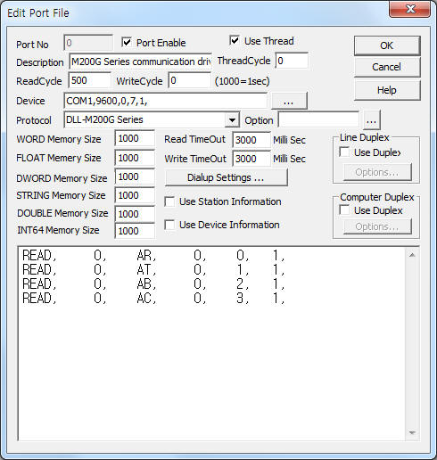
<Figure 1> is read setting example of M200G Series communication driver.
 |
| <Figure 1> Read setting example of M200G Series communication driver |
Device part of <Figure 1> input Com Port(COM1), Baud Rate(9600), Parity Bit(0), Data Bit(7), Stop Bit(1) respectively, according to controller.
Baud rate, parity bit, data bit, stop bit of M200G Series can set by using front operation button.( refer to Chapter 4 )
M200G Series communication driver read schedule
Read schedule setting parameters are as follows:
1) Station – don't care.
2) Read command – command = AR(flow), AT(accumulated), AB(pressure), AC(temperature) … ( refer to <Table 1> )
3) Read start address – don't care.
4) Save start address for Communication Server – Saving start address of Communication Server.
5) Read Size – fixed to 1.
Read schedule example)
READ, 0, AR, 0, 0, 1,
READ, 0, AT, 0, 1, 1,
READ, 0, AB, 0, 2, 1,
READ, 0, AC, 0, 3, 1,
<Table 1> is command and contents of M200G Series communication driver.
| command | Contents | Remarks |
| AR | read of flow rate | unit of set |
| AT | read of accumulated | |
| AB | read of pressure | |
| AC | read of temperature | |
| AM | change to meter unit(weight units) | |
| AP | change to British and American(weight units) | |
| AE | read of energy | only when calorimetry |
| AN | read of power | |
| AW | read of condensate temperature | |
| AV | change to meter unit(volumetric flow rate units) | only gas flow computer (M250G) |
| AW | change to British and American(volumetric flow rate units) | |
| <Table 1> Read command and contents of M200G Series communication driver | ||
M200G Series communication driver store the same data in WORD, DWORD, FLOAT, STRING(only unit related) memory, but the data format are different.
If you click the icon
![]() in protocol option part, you can see the dialog
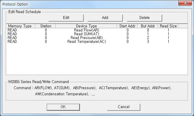
box such as <Figure 2>. you can also set read schedule by using this part.
in protocol option part, you can see the dialog
box such as <Figure 2>. you can also set read schedule by using this part.
 |
| <Figure 2> Example of M200G Series communication driver’s Option dialog box |
You can set read schedule by using
![]() ,
,
![]() ,
,
![]() button and listbox of <Figure 2>.
button and listbox of <Figure 2>.
 |
| <Figure 3> Example of M200G Series communication driver’s read schedule Add/Edit dialog box |
When you click Add button or Edit button in dialogue box of <Figure 2>, dialogue box of <Figure 3> will be shown.
You can read or control M200G Series controller by using 'writing settings'.
Digital Write
Digital write setting parameters are as follows:
1) PORT Port no. (0 ~ 255)
2) STATION don't care.
3) ADDRESS readed data saving start address for read command.
4) Extra1 command = AR(flow), AT(accumulated), AB(pressure), AC(temperature) … ( refer to <Table 1> )
5) Extra2 don't care.
Write example 1)
PORT:0, station:0, ADDRESS:0020, Extra1: AR, Extra2 : 0
The setting parameter shown above is flow rate reading example. After reading, the readed value save at 20 WORD, FLOAT, DWORD, STRING memory.
Write example 2)
PORT:0, station:0, ADDRESS:0021, Extra1: AT, Extra2 : 0
The setting parameter shown above is accumulated data reading example. After reading, the readed value save at 21 WORD, FLOAT, DWORD, STRING memory.
Write example 3)
PORT:0, station:0, ADDRESS:0022, Extra1: AB, Extra2 : 0
The setting parameter shown above is pressure data reading example. After reading, the readed value save at 22 WORD, FLOAT, DWORD, STRING memory.
Write example 4)
PORT:0, station:0, ADDRESS:0023, Extra1: AC, Extra2 : 0
The setting parameter shown above is temperature data reading example. After reading, the readed value save at 23 WORD, FLOAT, DWORD, STRING memory.
Analog Write
Analog write and digital write have the same setting parameters except output value.
M200G Series controller have to set commissioning when power is supplied again(or other reason) such as follows. ( can communicate with M200G controller )
1) ‘GB-D-F-E 1-2-3-4’(selection of language) will be display at front screen.
2) Please select language(1 = English, 2 = German, 3 = French, 4 = Spanish) by number and press 'ENTER' button. Then will be display ‘METER 0-1-2-3-4’(type of flow rate meter).
3) Please select flow meter(0 = flap, 1 = orifice, 2 = gilflo, 3 = vortex, 4 = ILVA).
4) Select '2' (gilflo) and press 'ENTER' button. Then, will be display ‘METRIC/IMP 0-1’(selection of unit).
5) Select '0'(METRIC) and press 'ENTER' button. Then, will be display ‘MAXF 0000000 KG/H’.
6) Please input 1380 ~ 1999999(equivalent amount of water, default = 1999999 ). Then will be display ‘DRYNESS = 100%’.
7) Input 'SRYNESS'( 100% ) and press 'ENTER' button. Then will be display ‘HEAT METER 0-1’(selection of meter).
8) Select measurement system( 0 = steam flow measurement ) and press 'ENTER' button. Then will be display ‘SUPERHEAT 0-1’.
9) Select Super heat( 0 = non super heat ) and press 'ENTER' button. Then will be display ‘T SENSOR 0-1’.
10) Select T Sensor existence( default : 1 = Existence ). Then, will be display ‘T MIN 100.0 ℃’(4mA).
11) Please input default setting( 100.0 ℃ ) and press 'ENTER' button. Then, will be display ‘T MAX 250.0 ℃’.
12) Please input default setting( 250.0 ℃ ) and press 'ENTER' button. Then, will be display ‘INPUT A = 000000’.
13) Please input default setting( 000000 ) and press 'ENTER' button. Then, will be display ‘INPUT B = 000000’.
14) Please input default setting( 000000 ) and press 'ENTER' button. Then, will be display ‘INPUT C = 000000’.
15) Please input default setting( 000000 ) and press 'ENTER' button. Then, will be display INPUT D = 000000’.
16) Please input default setting( 000000 ) and press 'ENTER' button. Then, will be display ‘INPUT E = 000000’.
15) Please input default setting( 000000 ) and press 'ENTER' button. Then, completed the setting of commissioning.
<Figure 4> is appearance of M200G Series flow meter.
 |
| <Figure 4> Appearance of M200G Series flow meter |
Baud rate, parity bit, data bit, stop bit of M200G Series can set by using front operation button refer to <Figure 4> ) such as follows.
1) Press 'CODE' button at normal operation.
2) Press 4 digit password( default password = 0000 ) and press 'ENTER' button.
3) ‘FUNCTION NO ?’ screen will be displayed when correct password.
4) Input '3 button and press 'ENTER'button. Then, will be display ‘BAUD 1- 9600’(9600, .. = current baud rate).
5) Input '1' button. Then, selected baud rate, the order of 1200, 4800, 9600, 19200.
6) After setting of baud rate, press 'ENTER' button. Then, will be display ‘STOP BITS 1-2’.
7) Input '1' or '2' button(selection of stop bit) and press 'ENTER' button. Then, will be display ‘DATA BITS 7-8’.
8) Input '7' or '8' button(selection of data bit) and press 'ENTER' button. Then, will be display ‘PARITY OFF0 ON1’.
9) Input '0' or '1' button(selection of parity bit) and press 'ENTER' button. Then, completed the setting of baud rate, etc and will be display ‘FUNCTION NO ?’ at screen.
10) At the ‘FUNCTION NO ?’ state, press 'ENTER' button. Then, will return to normal operation.
Connection of communication cable and main power are as follows.
Connection of communication cable
Please connect Tx, 0V, Rx connector of M200G Series and 2, 5, 3 pin of computer's 9pin connector such as follows.
RS-232C of M200G Series( refer to<Figure 5>) 9 pin connector of computer
19 connector (Tx) ------------------------------------------ 2 connector of RS232C (Rx)
17 connector (Rx) ------------------------------------------ 3 connector of RS232C (Tx)
18 connector (0V) ------------------------------------------ 5 connector of RS232C (Ground)
 |
| <Figure 5> Connection example of communication cable and main power to M200G Series |
Connection of main power
Please connect 220 ~ 240 V AC 50 ~ 60HZ( maximum 80mA) main power to N, L connector such as <Figure 5>.