Lonworks Object Server Read/Write communication driver for LG system air conditioning is the driver to communicate with BNU-LW equipment of LG in Korea.
Note) Lonworks Object Server Read/Write communication driver needed COM object of LonworksObjectServer 3.08(or compatible, have to install).
Also, you have to gegister 'Network DB', 'Sub System', 'Device' by using 'LonMaker for Windows'(etc) program.
When you install 'LonMaker for Windows', 'LonworksObjectServer( lcaobjsv.ocx )' is installed together.
Note) Lonworks Object Server Read/Write communication driver
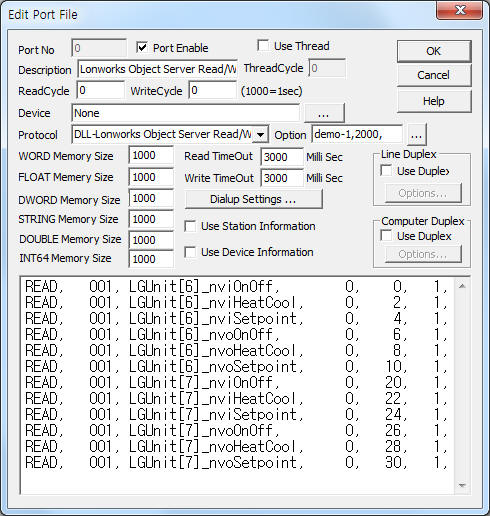
<Figure 1> is read setting example of Lonworks Object Server Read/Write communication driver for LG system air conditioning.
|
|
| <Figure 1> Read setting example of Lonworks Object Server Read/Write communication driver for LG system air conditioning |
Please input 'None' at Device part of <Figure 1>.
In protocol option part, you can set the following: Network DB name( demo, ... ), periodic read time for each point(0 = don't use periodic read, 1 ~ = periodic read time(milli second unit), Default = 0). Each argument is a comma-delimited.
Note) Lonworks Object Server Read/Write communication driver must not use 'Thread' option.
Lonworks Object Server Read/Write communication driver for LG system air conditioning read schedule
Read schedule setting parameters are as follows:
1) Name of Monitor Set – Monitor Set name of setting program.
2) Name of Monitor Point – Monitor Point name in Monitor Set.
3) Read start address – don't care.
4) Save start address for Communication Server – Saving start address of Communication Server.
5) Read Size – 1 ~ 256.
2 or grerter than = read from Monitor Point and next point.....
If a Monitor Point have multi data, you have to set 'read size' = 1.
Read schedule example)
READ, 001, LGUnit[6]_nviOnOff, 0, 0, 1,
READ, 001, LGUnit[6]_nviHeatCool, 0, 2, 1,
READ, 001, LGUnit[6]_nviSetpoint, 0, 4, 1,
READ, 001, LGUnit[6]_nvoOnOff, 0, 6, 1,
READ, 001, LGUnit[6]_nvoHeatCool, 0, 8, 1,
READ, 001, LGUnit[6]_nvoSetpoint, 0, 10, 1,
READ, 001, LGUnit[7]_nviOnOff, 0, 20, 1,
READ, 001, LGUnit[7]_nviHeatCool, 0, 22, 1,
READ, 001, LGUnit[7]_nviSetpoint, 0, 24, 1,
READ, 001, LGUnit[7]_nvoOnOff, 0, 26, 1,
READ, 001, LGUnit[7]_nvoHeatCool, 0, 28, 1,
READ, 001, LGUnit[7]_nvoSetpoint, 0, 30, 1,
Lonworks Object Server Read/Write communication driver store the same data in WORD, DWORD, FLOAT memory, but the data format are different.
Also, save readed string data at STRING memory.
If you click the icon
![]() in protocol option part, you can see the dialog
box such as <Figure 2>. you can also set Monitor Set, read schedule,
Network DB name, periodic read time by using this part.
in protocol option part, you can see the dialog
box such as <Figure 2>. you can also set Monitor Set, read schedule,
Network DB name, periodic read time by using this part.
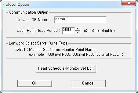 |
| <Figure 2> Example of Lonworks Object Server Read/Write communication driver’s protocol option dialog box |
When you click ![]() button in
dialog box
of <Figure 2>, dialog box of <Figure 3> will be shown.
button in
dialog box
of <Figure 2>, dialog box of <Figure 3> will be shown.
Note) <Figure 3> dialog box is execution example of ‘program folder\Protocol\RegMonSet.exe’.
You can run this program for Monitor Set(Point), but read schedule can set by using <Figure 2>.
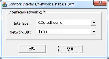 |
| <Figure 3> Dialog box example for Lonwork Interface/Network Database selection |
When you click ![]() button of
<Figure 3>, dialog box of <Figure 4> will be shown.
button of
<Figure 3>, dialog box of <Figure 4> will be shown.
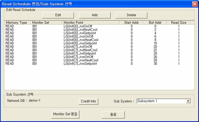 |
| <Figure 4> Dialog box example for read schedule and sub system selection |
You can set read schedule by using
![]() ,
,
![]() ,
,
![]() button and listbox of <Figure 4>.
button and listbox of <Figure 4>.
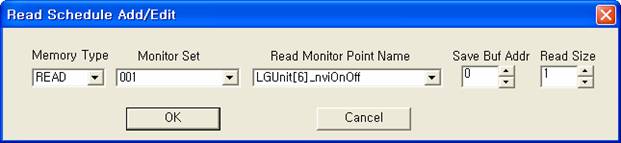 |
| <Figure 5> Example of Lonworks Object Server Read/Write communication driver’s read schedule Add/Edit dialog box |
When you click Add button or Edit button in dialog box of <Figure 4>, dialog box of <Figure 5> will be shown.
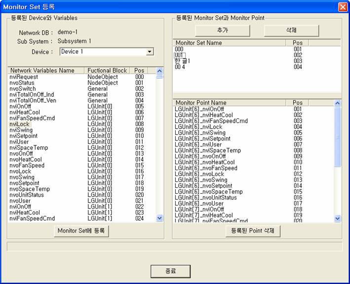
<Figure 6> is dialog box example for Monitor Set registration dialog box.
You can select Monitor Set registration dialog box by clicking ![]() button at <Figure 4>
after selection ‘Sub System’.
button at <Figure 4>
after selection ‘Sub System’.
 |
| <Figure 6> Example of Monitor Set registration dialog box |
Left list of <Figure 6> is Network Variables(Point) in current Device, right list are registered Monitor Set(upper) and Monitor Point.
You can add, delete(Monitor Set) by using ![]() ,
, ![]() button of
<Figure 6>.
button of
<Figure 6>.
After selecting the
Network Variable, click ![]() button,
you can register Monitor Point.
button,
you can register Monitor Point.
By using ![]() button,
you can delete registered Monitor Point.
button,
you can delete registered Monitor Point.
The method of multiple selection of Network Variable or Monitor Point : by using Shift, Ctrl key.(for register of delete)
Download of RegMonSet.exe file
You can control the value of Monitor Point by using 'writing settings'.
Digital Write
Digital write setting parameters are as follows:
1) PORT Port no. (0 ~ 255)
2) STATION Command type.
255 : setting command of Credit Info,
254 : read command of Credit Info, ( refer to <Table 1> ),
Monitor Point name = ***_nviModify(*** : Functional Block name) : 0 ~ 5 variable type,( refer to <Table 2> )
other : don't care.
3) ADDRESS Writing address for multi point.
Monitor Point name = **_nviModify(*** : Functional Block name) : Index number,( refer to <Table 2> )
4) Extra1 Monitor Set name.Minitor Point name.
can input registered Monitor Set and Point, Note) delimiter : . ( dot )
Monitor Point name = ***_nviModify(*** : Functional Block name) : nvoV1_15, ... internal value, refer to <Table 2>,
Monitor Point name ***_nviHeatCool(*** : Functional Block name) : setting of HVAC(system air conditioning) operation mode, refer to <Table 3>,
Station = 255 : input Customer ID.Customer Key value,
Station = 254 : save reade Credit status value from Address, ( refer to <Table 1>)
5) Extra2 selection of multi point. 0 = single point, 1 = multi point.
When Monitor Point name = **_nviModify(*** : Functional Block name) : variable value Mode(0 = AUTOMATIC, 1 = MANUAL),( refer to <Talbe 2> )
<Table 1> is data saving address and contents for Credit Info read command.
| Data saving address | Contents | Remarks |
| Address + 0 | License Type | 0 = Legacy or demo mode, 1 = Standard mode(key lock normal status) |
| Address + 1 | remaining until expiration date | 255 = normal operation, other = demo mode, ... |
| Address + 2 | count of Licensed Credit | |
| Address + 3 | count of used Credit | |
| Address + 4 | count of max Deficit Credit | |
| Address + 5 | count of Deficit Credit | |
| <Table 1> Data saving address and contents for Credit Info read command | ||
<Table 2> is writing parameters for nviModify point.
| Parameter for write | Range | Setting value |
| Port | 0 ~ 255 | Port no. (0 ~ 255) |
| Station | 0 ~ 5 | 0 = VARIABLE, 1 = CONSTANT, 2 = INPUT, 3 = OUTPUT, 4 = CONTROLLER, 5 = TIMER |
| Address | 0 ~ | 1 ~ range of internal variable (nvoV1_15, ...) |
| Extra1 | ???.***_nviModify | ??? = registered Monitor Set name, ***_nviModify = Monitor Point name (*** : Functional Block name) |
| Extra2 | 0 ~ 1 | 0 = AUTOMATIC, 1 = MANUAL |
| Output value | Interger of float value | writing value |
| <Table 2> Writing parameters for nviModify point | ||
<Table 3> is writing parameters for nviHeatCool point.
| Parameter for write | Range | Setting value |
| Port | 0 ~ 255 | Port no. (0 ~ 255) |
| Station | don't care | |
| Address | ||
| Extra1 | ???.***_nviHeatCool | ??? = registered Monitor Set name, ***_ nviHeatCool = Monitor Point name (*** : Functional Block name) |
| Extra2 | don't care | |
| Output value | Interger of float value | 0 = HVAC_NUL, 1 = HVAC_AUTO, 2 = HVAC_HEAT, 3 = HVAC_MRNG_WRMUP, 4 = HVAC_COOL, 5 = HVAC_NIGHT_PURGE, 6 = HVAC_PRE_COOL, 7 = HVAC_OFF, 8 = HVAC_TEST", 9 = HVAC_EMERG_HEAT, 10 = HVAC_FAN_ONLY, 11 = HVAC_FREE_COOL, 12 = HVAC_ICE, 13 = HVAC_MAX_HEAT, 14 = HVAC_ECONOMY, 15 = HVAC_DEHUMID
(***_nviModify read value : 0 ~ 15) |
| <Table 3> Writing parameters for nviHeatCool point | ||
Write example 1)
PORT:0, station:0, ADDRESS:0001, Extra1:001.LGUnit[6]_nviOnOff, Extra2 : 1
The setting parameter shown above is control example of LGUnit[6]_nviOnOff(system air conditioning On/Off point, address = 6) Monitor Point in 001 Monitor Set.
Write example 2)
PORT:0, station:0, ADDRESS:0001, Extra1:001. LGUnit[7]_nviOnOff, Extra2 : 1
The setting parameter shown above is control example of LGUnit[7]_nviOnOff(system air conditioning On/Off point, address = 7) Monitor Point in 001 Monitor Set.
Analog Write
Analog write and digital write have the same setting parameters except output value.
Write example 1)
PORT:0, station:0, ADDRESS:0000, Extra1:001.LGUnit[6]_nviSetpoint, Extra2 : 0
The setting parameter shown above is setting example of LGUnit[6]_nviSetpoint(temperature setting for Address = 6) Monitor Point in 001 Monitor Set.
Write example 2)
PORT:0, station:0, ADDRESS:0000, Extra1:001.LGUnit[6]_nviHeatCool, Extra2 : 0, Output value = 2
The setting parameter shown above is setting example of LGUnit[6]_nviHeatCool(operation mode setting for Address = 6) Monitor Point in 001 Monitor Set. ( output value 2 = HEAT, refer to <Table 3> )
Write example 3)
PORT:0, station:0, ADDRESS:0000, Extra1:001.LGUnit[6]_nviHeatCool, Extra2 : 0, Output value = 4
The setting parameter shown above is setting example of LGUnit[6]_nviHeatCool(operation mode setting for Address = 6) Monitor Point in 001 Monitor Set. ( output value 2 = COOL, refer to <Table 3> )
<Figure 7> is wiring of BNU-LW and other equipment for LG system air conditioning.
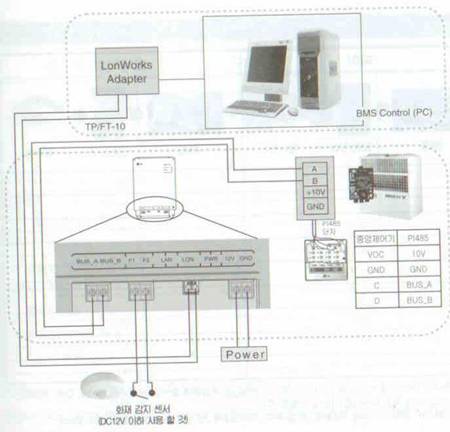 |
| <Figure 7> Wiring of BNU-LW and other equipment for LG system air conditioning |
For communicate with Lonworks communication by using BNU-LW equipment( lower of <Figure 7> ), needed PI-485 communication card at system air conditioning.
Also, should be installed Lonworks Adapter between computer and BNU-LW.
<Figure 8>, <Figure 9> are appreance of Lonworks Adapter and BNU-LW.
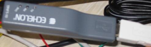 |
| <Figure 8> Appreance of Lonworks Adapter |
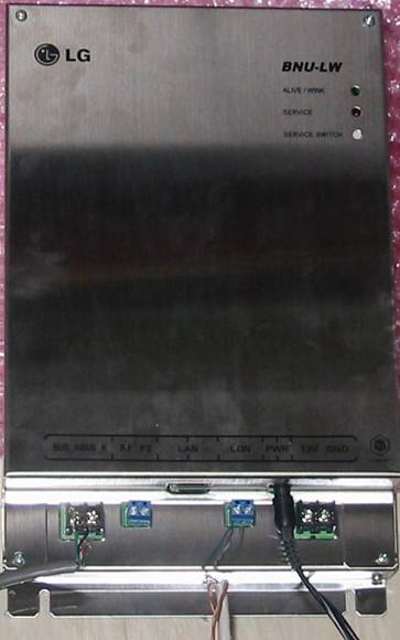 |
| <Figure 9> Appreance of BNU-LW |
Note) LG System Air Conditioner PI-485 communication driver(refer to PI-485 setting, ...)