LA250 communication driver is the driver to communicate with controller(MK250) of ASR.
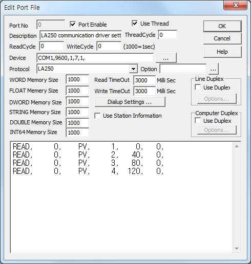
<Figure 1> is read setting example of LA250 communication driver.
 |
| <Figure 1> Read setting example of LA250 communication driver |
Device part of <Figure 1> input Com Port(COM1), Baud Rate(9600), Parity Bit(1), Data Bit(7), Stop Bit(1) respectively, according to controller.
Baud rate of LA250 can set at controller, but Parity Bit, Data Bit, Stop Bit are fixed to 1, 7, 1.
LA250 communication driver read schedule
1) Station – don't care.
2) Read command – Command = PV, DI, SV, ....
3) Read slot number – 1 ~ 24 slot number.
4) Save start address for Communication Server – Saving start address of Communication Server.
5) Read Size – Fixed to 40 word.
Read schedule example)
READ, 0, PV, 1, 0,
READ, 0, PV, 2, 40,
READ, 0, PV, 3, 80,
READ, 0, PV, 4, 120,
LA250 controller have 24(1 ~ 24 address) slot, so you can set slot number for read or write.
A slot have 40 word data. The data have alarm setting value,P,I,D,...( 17 setting value ), current value, status of controller.
<Table 1> is data saving address and contents for a slot data.
<Table 2> is bit data for each slot status.
| Data savint address | Size | Contents |
| Start addr + 0~1 | 2 | measurement value |
| Start addr + 2~4 | 3 | don't use |
| Start addr + 5 | 1 | status of slot |
| Start addr + 6~7 | 2 | setting of SV-H control |
| Start addr + 8~9 | 2 | setting of SV-L control |
| Start addr + 10~11 | 2 | setting of AL-H control |
| Start addr + 12~13 | 2 | setting of AL-L control |
| Start addr + 14~15 | 2 | H.ON TIME |
| Start addr + 16~17 | 2 | H.OFF TIME |
| Start addr + 18~19 | 2 | L.ON TIME |
| Start addr + 20~21 | 2 | L.OFF TIME |
| Start addr + 22~23 | 2 | output of counter regulation |
| Start addr + 24~25 | 2 | ON Tele Timer |
| Start addr + 26~27 | 2 | P(Proportional control) |
| Start addr + 28~29 | 2 | I(Integral control) |
| Start addr + 30~31 | 2 | D(Differential control) |
| Start addr + 32~33 | 2 | H output regulation |
| Start addr + 34~35 | 2 | L output regulation |
| Start addr + 36~37 | 2 | deadband |
| Start addr + 38~39 | 2 | proportional sync |
| <Table 1> Data saving address and contents for a slot data | ||
| bit | Contents |
| 0 | Slot ON/OFF |
| 1 | Remote/Local status |
| 2 | Control Hi output status |
| 3 | Control Lo output status |
| 4 | Alarm Hi output status |
| 5 | larm Lo output status |
| <Table 2> Bit data for each slot status | |
Readed values of LA250 communication driver are float data, so you have to set 'Float' data at Analog Input tag.( Filter = no calculate )
You can control LA250 controller by using 'writing settings'.
Digital Write
Digital write setting parameters are as follows:
1) PORT Port no. (0 ~ 255)
2) STATION don't care.
3) ADDRESS higher 3 digit : slot number(decimal unit),
lower 1 digit : selection of control, 0 = Start/Stop, 1 = Remote/Local
4) Extra1 don't care.
5) Extra2 don't care.
Write example 1)
PORT:0, station:0, ADDRESS:0110, Extra1: , Extra2 : 0
The setting parameter shown above is a Start(On)/Stop(Off) control example for 11 slot.
Analog Write
Analog write setting parameters are as follows:
1) PORT Port no. (0 ~ 255)
2) STATION don't care.
3) ADDRESS writing address : higher 2 digit = slot number(decimal unit), lower 2 digit = 3 ~ 19, selection of setting value. ( 3 = setting of SV-H control, ~ 19 = proportional sync setting, refer to <Table 1> )
4) Extra1 don't care.
5) Extra2 don't care.
Write example 1)
PORT:0, station:0, ADDRESS:1408, Extra1: , Extra2 : 0
The setting parameter shown above is H.OFF TIME setting example for 14 slot.
Check point when error of 'don't exist Slot'
An error of 'don't exist Slot', occurs when communication module of LA250 does not recognize that slot.
In this case, check install of communication IC in the slot of LA250(MK-250).
If communication IC is installed, please check connection line between LA250(MK-25) and communication module. (also check connection status, noise of inverter )