KNF SIMDOS 02 is a driver for communicating with KNF's diaphragm liquid pump.
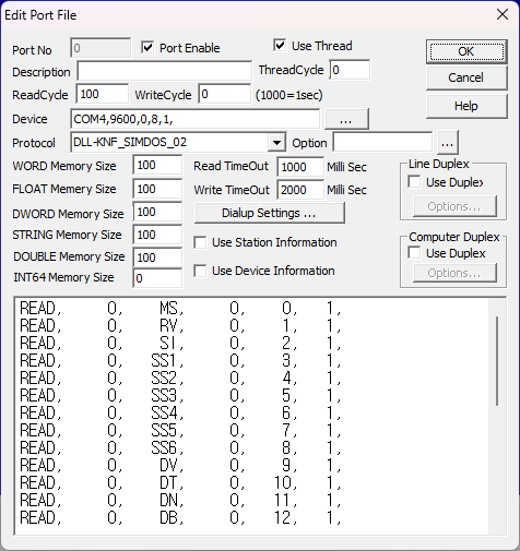
Figure 1 shows an example of communication settings when using the KNF SIMDOS 02 driver.
<Figure 1> Example of KNF SIMDOS 02 communication settings
In Figure 1, the DEVICE section contains the communication settings for KNF SIMDOS 02 in the following order, separated by commas (,): Baud Rate (9600), Parity Bit (0), Data Bit (8), Stop Bit (1)
Note: The current KNF SIMDOS 02 device's communication settings are fixed at 9600, 0, 8, 1.
| READ | Staion | Commnad | Start Address ( not used ) |
Memory buffer | Read Size |
| READ, | 1, | MS, | 0, | 0, | 1, |
| READ, | 1, | RV, | 0, | 1, | 1, |
| READ, | 1, | SI, | 0, | 2, | 1, |
| READ, | 1, | SS1, | 0, | 3, | 1, |
| READ, | 1, | SS2, | 0, | 4, | 1, |
| READ, | 1, | SS3, | 0, | 5, | 1, |
| READ, | 1, | SS4, | 0, | 6, | 1, |
| READ, | 1, | SS5, | 0, | 7, | 1, |
| READ, | 1, | SS6, | 0, | 8, | 1, |
| READ, | 1, | DV, | 0, | 9, | 1, |
| READ, | 1, | DT, | 0, | 10, | 1, |
| READ, | 1, | DN, | 0, | 11, | 1, |
| READ, | 1, | DB, | 0, | 12, | 1, |
| READ, | 1, | RA, | 0, | 13, | 1, |
| READ, | 1, | RB, | 0, | 14, | 1, |
| READ, | 1, | RS, | 0, | 15, | 1, |
| READ, | 1, | LC, | 0, | 16, | 1, |
| READ, | 1, | CC, | 0, | 17, | 1, |
| READ, | 1, | LS, | 0, | 18, | 1, |
| READ, | 1, | CH, | 0, | 19, | 1, |
| READ, | 1, | MP, | 0, | 20, | 1, |
| READ, | 1, | SA, | 0, | 21, | 1, |
| READ, | 1, | AD, | 0, | 22, | 1, |
| READ, | 1, | SP, | 0, | 23, | 1, |
| READ, | 1, | SV, | 0, | 24, | 1, |
| READ, | 1, | TT, | 0, | 25, | 1, |
| READ, | 1, | TV, | 0, | 26, | 1, |
| READ, | 1, | L1, | 0, | 27, | 1, |
| READ, | 1, | L2, | 0, | 28, | 1, |
Table 1: Examples of READ commands for KNF SIMDOS 02 driver
1) Station: Device address (station) number (0 ~ 98)
2) Command: Command word (See Table 1)
3) Start Address: Not used (fixed at 0)
4) Memory Location: Buffer location to store the read state value
5) Read Size: Size to read (fixed at 1)
Note: Values read from KNF SIMDOS 02 driver are stored in the same byte order as WORD, DWORD.
For data values with decimal points, the device sends values multiplied by 100, so the actual values should be adjusted by dividing by 100 in the program.
Storage locations can be modified by editing the READ request commands.
For detailed information about commands, please refer to the KNF SIMDOS 02 Communication Protocol manual.
| Command | Description | Read/Write | Memory Location |
Value Range/Description |
|---|---|---|---|---|
| MS | Operation Mode Selection | Read/Write | 0 |
0: Run Mode (Factory default) 1: Dispense Mode ml and time 2: Dispense Mode ml/min and time |
| RV | Flow Rate | Read/Write | 1 | 30~20,000 μl/min (Based on SIMDOS 02) |
| SI | Comm. Check | Read only | 2 | Return the currently set pump address (00-98) |
| SS1 | Operation Status | Read only | 3 |
Bit 0: Motor rotation status Bit 1: Pump fault Bit 2: Display status |
| SS2 | System Status | Read only | 4 |
Bit 0: Motor Adjustment Status Bit 1: I/O 1 input Bit 2: I/O 2 input Bit 3: Motor UT status |
| SS3 | Run Mode Status | Read only | 5 | Bit 0: Run Mode Operation Status |
| SS4 | Dispense Mode Status | Read only | 6 |
Bit 0: Dispense Mode Operation Status Bit 3: User Stop Status |
| DV | Dispense Volume | Read/Write | 9 | 30~999,999 μl |
| DT | Dispense Time | Read/Write | 10 | Time format: [hh:mm:ss.ss] |
| DN | Dispense Count | Read/Write | 11 |
0: Function OFF 1: Disable 2-999: Iterations 1000: Infinite loop |
| DB | Break Time | Read/Write | 12 | 1~5999 seconds |
| RA | Analog Input Type | Read/Write | 13 |
0: 0-10V 1: 0-20mA 2: 4-20mA 3: 0-5V 9: Analog OFF |
| RB | Analog Range | Read/Write | 14 |
0: 1-100% of full scale 1: 0.3-30% of full scale 2: 0.15-15% of full scale |
| RS | Output Function | Read/Write | 15 |
0: Alarm on Error 1: Motor Running 2: Volume Finish 3: Revolution Pulse 4: Volume Pulse |
| LC | LCD Contrast | Read/Write | 16 | 0-100 |
| CC | Pump Profile | Read/Write | 17 |
0: Standard 1: Volatile Fluids 2: Viscous Fluids 3: High Viscous Fluids |
| LS | Language | Read/Write | 18 |
0: English 1: German 2: French 3: Spanish 4: Italian 5: Chinese 6: Japanese |
| CH | Calibration Factor | Read/Write | 19 | 80.00-120.00% (8000-12000) |
| MP | Maintenance Position | Read/Write | 20 |
0: Normal 1: Maintenance |
| SA | Auto Start | Read/Write | 21 |
0: Inactive 1: Active |
| AD | Pump Address | Read/Write | 22 | 00-98 (99 is for simultaneous control) |
| SP | Protocol Answer | Read/Write | 23 |
0: Protocol answer inactive 1: Protocol answer active (ACK/NACK respose) *1 to communicate. |
| SV | Version Info | Read/Write | 24 |
10 digits: First 5 digits: Pump model (e.g. 00102 = FEM1.02) Last 5 digits: Firmware version (e.g. 01307 = Ver 1.307) *It is also stored in STRING memory. |
| TT | Time Counter | Read/Write | 25 |
Time Counter in Dispense/Run Mode Format: [hh:mm:ss.ss] Reset to 0 on startup |
| TV | Volume Counter | Read/Write | 26 |
Volume counter in Dispense/Run mode Unit: μl Max. : 999,999,999 μl |
| L1 | Digital Input 1 | Read/Write | 27 |
00: Signal Off (Factory Default) 01: Level controlled Start/Stop 06: Edge controlled Start/Stop |
| L2 | Digital Input 2 | Read/Write | 28 |
00: Signal Off (Factory Default)) 01: Level controlled Start/Stop 06: Edge controlled Start/Stop 08: Error reset & Pump Stop on edge 09: Prime/Drain on level, Error reset on edge 10: Error reset on edge, Prime/Drain after 1s on level |
Table 2: Data storage locations and contents for KNF SIMDOS 02 driver
![]() in the Protocol Options section, the dialog box shown
in the Protocol Options section, the dialog box shown
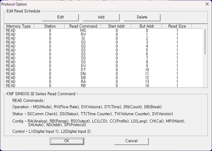
<Figure 2> Communication Settings dialog box for KNF SIMDOS 02 drive
You can use buttons and list boxes to set reading schedules in <Figure 2> ![]() ,
, ![]() ,
, ![]()
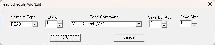
<Figure 3>
<Figure 3>is the dialog box that appears when you add or edit a reading schedule in the dialog box in <Figure 2>.
Data can be written using digital/analog output commands
| Command | Description | Read/Write | Value Range/Description |
|---|---|---|---|
| KY | Start/Stop Control | Write only |
0: Stop (Factory Default) 1: Start (Auto-start Setting) 2: Prime/Drain (1 stroke) 3: Pause |
| CF | Customer Calibration Volume | Write only |
Run mode: μl/min unit Dispense mode: μl unit, Input of actual measurements for calibration (8 digits) |
| IN | Initialize Pump | Write only |
Pump Restart Command Same effect as power OFF/ON Used to recover after motor error or overpressure error |
| IP | Factory Reset | Write only |
Factory Reset Commands Reset all settings except the pump address Restore all corrections to factory settings as well |
Table 3: Write-only commands for KNF SIMDOS 02 driver
Digital output settings are similar to analog output settings but use only values (0, 1).
Data can be read and set using analog output.
Required elements for analog output TAG settings:
1) PORT: Communication port number for KNF SIMDOS 02 driver (0 ~ 255)
2) STATION: Device address (station) number (0 ~ 98) *99 is for simultaneous control of all pumps
3) Address: Not used
4) Extra1: Write command. Can use Read/Write or Write-only commands from Tables 1 and 3
5) Extra2: Not used
Example 1) When setting Station: 0, Address: 0000, Extra1: MS, EXTRA2: 0 and using analog output, you can change the Run Mode of the KNF SIMDOS 02 device with address (station) 0 to the specified value.
Example 2) When setting Station: 1, Address: 0000, Extra1: RV, EXTRA2: 0 and using analog output, you can change the Flow rate of the KNF SIMDOS 02 device with address (station) 1 to the specified value.
Example 3) When setting Station: 1, Address: 0000, Extra1: AD, EXTRA2: 0 and using analog output, you can change the address (station) of the KNF SIMDOS 02 device with address 1 to the specified value.
Example 4) When setting Station: 99, Address: 0000, Extra1: AD, EXTRA2: 0 and using analog output, you can change the address (station) of all connected KNF SIMDOS 02 devices to the specified value.
Example 5) When setting Station: 1, Address: 0000, Extra1: IP, EXTRA2: 0 and using analog output, you can reset the KNF SIMDOS 02 device with address 1 to factory settings.
Example 6) When setting Station: 1, Address: 0000, Extra1: SP, EXTRA2: 0 and using analog output, you can change the communication response settings of the KNF SIMDOS 02 device with address (station) 1.
Note: The DLL-KNF_SIMDOS_02 driver requires SP (Protocol answer setting) to be set to 1 for proper communication.