KEN-2000N Power Meter communication driver is the driver to communicate with power meter controller of KD Power Co,. Ltd. in Korea.
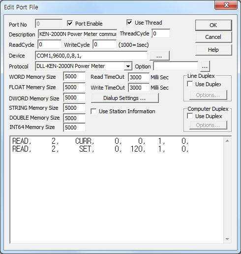
<Figure 1> is read setting example of KEN-2000N Power Meter communication driver.
 |
| <Figure 1> Read setting example of KEN-2000N Power Meter communication driver |
Device part of <Figure 1> input Com Port(COM1), Baud Rate(9600), Parity Bit(0), Data Bit(8), Stop Bit(1) respectively, according to controller.
Note) Baud rate, parity bit, data bit stop bit of KEN-2000N controller are fixed to 9600, 0, 8, 1.
KEN-2000N Power Meter communication driver read schedule
Read schedule setting parameters are as follows:
1) Station – 0 ~ 255 station number of KEN-2000N Power Meter.
2) Read command – CURR, SET. ( refer <Table 1> ~ <Table 4> )
CURR : read of measurement value,
SET : read of setting value.
3) Read start address – Don't care.
4) Save start address for Communication Server – Saving start address of Communication Server.
5) Read Size – Fixed to 1. ( CURR = 110, SET = 9 )
6) Controller type – 1 = MCC 2060, 2 = AA382I, 0,... = KEN 2000N.
Read schedule example)
READ, 2, CURR, 0, 0, 1, 0,
READ, 2, SET, 0, 120, 1, 0,
Note) refer to setting of MCC 2060 controller
<Table 1>, <Table 2> are data saving address and contnets of CURR read command. ( <Table 2> = for KEN-AA382I Power Meter )
<Table 3> is unit value and contents for KEN-2000N/AA382I Power Meter.
<Table 4> is data saving address and contnets of SET read command.
| Data saving address | Contents | Remarks |
| 0 | voltage of L1 | 3digit number |
| 1 | voltage unit of L1 |
|
| 2 ~ 5 | voltage and unit of L2, L3 | voltage, unit, voltage, unit, ・ |
| 6 ~ 11 | current and unit of I1, I2, I3 | |
| 12 ~ 17 | COSフ value and unit of L1, L2, L3 | |
| 18 ~ 23 | C.F. value and unit of L1, L2, L3 | |
| 24 ~ 29 | VAR value and unit of L1, L2, L3 | |
| 30 ~ 35 | W value and unit of L1, L2, L3 | |
| 36 ~ 41 | VA value and unit of L1, L2, L3 | |
| 42 ~ 45 | 3フ voltage and unit, 3フ current and unit | |
| 46 ~ 51 | 3フCOSフ value and unit, 3フVar value and unit, 3フW value and unit | |
| 52 ~ 55 | 3フVA value and unit, Hz value and unit | |
| 56 ~ 59 | temperature value and unit of Trans, Pannel | |
| 60 ~ 63 | W vaule and unit of Peak Demand, Demand W | |
| 64 ~ 67 | value and unit of WH, Sub WH | 6 digit number |
| 68 ~ 72 | current year, month, day, hour, minute |
|
| 73 ~ 78 | 1st voltage and unit of L1, L2, L3 | voltage, unit, voltage, unit, ・ |
| 79 ~ 84 | 1st current and unit of L1, L2, L3 | |
| 85 ~ 86 | W value and unit of Count Demand | |
| 87 ~ 88 | syncronization time minute, second | 2 digit number |
| 89 | cutoff (RMT) value |
|
| 90 ~ 91 | value and unit of unblanced factor |
|
| 92 ~ 93 | PEAK1, PEAK2 | 0 = relay OFF, 1 = relay ON |
| 94 ~ 95 | COSフ1, COSフ2 | |
| 96 ~ 97 | TR-H, PN-H | 1 = alarm of temperature |
| 98 ~ 99 | CB off, CB trip | 1 = CB off or trip status |
| 100 | unbalance | 1 = unbalance status |
| 101 | TR-HH, LINE | 1 = TR temperature HH status(cutoff) |
| 102 | LINE | 1 = LINE connection status(cutoff) |
| 103 | OVER | 1 = OVER status |
| 104 ~ 108 | current year, month, day, hour, minute |
|
| 109 | type of connection | 0 : DELTA, 1 : STAR, 2 : 1P3W |
| <Table 1> Data saving address and contnets for CURR read command | ||
| Data saving address | Contents | Remarks |
| 0 | voltage of L1 | 3digit number |
| 1 | voltage unit of L1 |
|
| 2 ~ 5 | voltage and unit of L2, L3 | voltage, unit, voltage, unit, ・ |
| 6 ~ 11 | current and unit of I1, I2, I3 | |
| 12 ~ 17 | COSフ value and unit of L1, L2, L3 | |
| 18 ~ 23 | C.F. value and unit of L1, L2, L3 | |
| 24 ~ 29 | VAR value and unit of L1, L2, L3 | |
| 30 ~ 35 | W value and unit of L1, L2, L3 | |
| 36 ~ 41 | VA value and unit of L1, L2, L3 | |
| 42 ~ 45 | 3フ voltage and unit, 3フ current and unit | |
| 46 ~ 51 | 3フCOSフ value and unit, 3フVar value and unit, 3フW value and unit | |
| 52 ~ 55 | 3フVA value and unit, Hz value and unit | |
| 56 ~ 59 | temperature value and unit of Trans, Pannel | |
| 60 ~ 63 | W vaule and unit of Peak Demand, Demand W | |
| 64 ~ 67 | value and unit of WH, Sub WH | 6 digit number |
| 68 ~ 72 | current year, month, day, hour, minute |
|
| 73 ~ 78 | 1st voltage and unit of L1, L2, L3 | voltage, unit, voltage, unit, ・ |
| 79 ~ 84 | 1st current and unit of L1, L2, L3 | |
| 85 ~ 86 | W value and unit of Count Demand | |
| 87 ~ 88 | value and unit of unblanced factor |
|
| 89 ~ 90 | PEAK1, PEAK2 | 0 = relay OFF, 1 = relay ON |
| 91 ~ 92 | COSフ1, COSフ2 | |
| 93 ~ 94 | ALM1, ALM2 | 0 Alarm Off, 1 = Alarm On |
| 95 | TR-HH | 1 = temperature ON status, 0 = alarm Off status |
| 96 | IN-OPEN | |
| 97 | MAIN-SW | |
| 98 | ACB1 | |
| 99 | TR-H | |
| 100 | OVER-load | |
| 101 | BALAN | |
| 102 | PEAK-ready | |
| 103 | PN TEMP | |
| 104 ~ 108 | current year, month, day, hour, minute |
|
| <Table 2> Data saving address and contnets of CURR read command for KEN-AA382I Power Meter | ||
value for unit |
Contents |
0 |
M |
1 |
none |
2 |
K |
3 |
M |
4 |
G |
| <Table 3> Unit value and contents for KEN-2000N/AA382I Power Meter | |
| Data saving address | Contents |
Remarks |
0 |
P.F.L. |
3 digit number |
1 |
reserved |
|
2 |
UNBALANCE |
|
3 ~ 4 |
PEAK value and unit |
4 digit number |
5 |
PT-1 |
6 digit number |
6 |
CT-1 |
|
7 |
TR-H |
3 digit number (AA382I = don't exist) |
8 |
PN-H |
|
| <Table 4> Data saving address and contnets of SET read command | ||
Please refer to 'Manual of KEN-2000N Power Meter Controller' for more information.
KEN-2000N Power Meter communication driver store the same data in WORD, DWORD, FLOAT memory, but the data format are different.
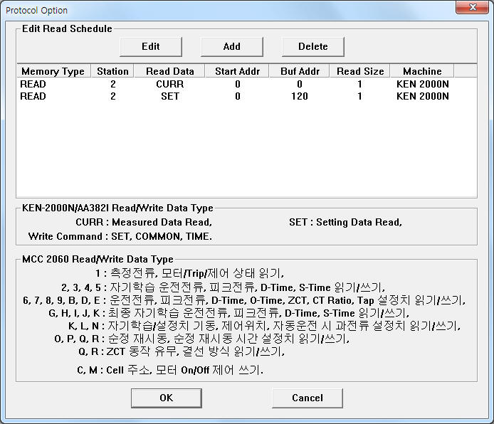
If you click the icon ![]() in protocol option part at
<Figure 1>, you
can see the dialogue box such as <Figure 2>. you can also set read schedule by
using this part.
in protocol option part at
<Figure 1>, you
can see the dialogue box such as <Figure 2>. you can also set read schedule by
using this part.
 |
| <Figure 2> Example of KEN-2000N Power Meter communication driver¨s Option dialog box |
You can set read schedule by using ![]() ,
, ![]() ,
, ![]() button and listbox of <Figure
2>.
button and listbox of <Figure
2>.
 |
| <Figure 3> Example of KEN-2000N Power Meter communication driver¨s read schedule Add/Edit dialog box |
When you click Add button or Edit button in dialogue box of <Figure 2>, dialogue box of <Figure 3> is shown.
You can control KEN-2000N controller by using 'writing settings'.
Digital Write
Digital write and analog write have the same setting parameters except output value.
Analog Write
Analog write setting parameters are as follows:
1) PORT Port no. (0 ~ 255)
2) STATION 0 ~ 255 station number of KEN-2000N Power Meter.
3) ADDRESS SET, COMMON command – writing address(0 ~ 99, refer to <Table 5>), TIME command - Don't care.
4) Extra1 Write command
SET – data setting command,
COMMON - output of common setting,
TIME - time syncronization with computer.
5) Extra2 Controller type. 1 - MCC 2060, 2 - AA382I, 0 - KEN-2000N.
<Table 5> is address and contents for SET write command.
ADDRESS |
Contents |
Remarks |
0 |
P.F-L |
50 ~ 99 % |
2 |
UNBALANCE |
1 ~ 100 (100 =unblanced factor control OFF) |
3 |
PEAK DEMAND |
1 ~ 9999 : W unit ( 1 ), 1 ~ 9999 : KW unit ( 2 ), 1 ~ 100 : MW unit ( 3 ) |
4 |
TR-H |
1 ~ 150 (only KEN-200N model) |
5 |
PN-H |
|
97 |
signal of cut off |
2 : cut off relay ON |
98 |
signal of return |
1 : return relay ON |
99 |
SUB WH reset |
1 : SUB Total reset |
| <Table 5> Address and contents for SET write command | ||
Write example 1)
PORT:0, station:1, ADDRESS:0000, Extra1: SET, Extra2 : 0
The setting parameter shown above is a setting example of P.F-L value(50 ~ 99).
Write example 2)
PORT:0, station:1, ADDRESS:0099, Extra1: SET, Extra2 : 0
The setting parameter shown above is SUB WH reset example of 1 station number KEN-2000N Power Meter.
Write example 3)
PORT:0, station:1, ADDRESS:0000, Extra1: TIME, Extra2 : 0
The setting parameter shown above is time syncronization with computer example of 1 station number KEN-2000N Power Meter.
Please connect A2(+), B2(-) connector(RS-485) of KEN-2000N and Tx+(Rx+), T-(Rx-) of computer such as <Figure 4>.
<Figure 4>, <Figure 5> are connection example of communication cable and main power to KEN-2000N and KD-AA382I Power Meter.
<Figure 6> is appearance of KD-AA382I Power Meter.
computer KEN-2000N Power Meter
 |
| <Figure 4> Connection example of communication cable and main power to KEN-2000N Power Meter |
 |
| <Figure 5> Connection example of communication cable and main power to KD-AA382I Power Meter |
 |
| <Figure 6> Appearance of KD-AA382I Power Meter |