KACO XP100-HV Inverter Communication Driver is the driver to communicate with inverter controller of KACO Geratetechnic GmbH in Germany.
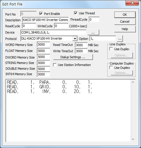
<Figure 1> is read setting example of KACO XP100-HV Inverter communication driver.
 |
| <Figure 1> Read setting example of KACO XP100-HV Inverter communication driver |
Device part of <Figure 1> input Com Port(COM1), Baud Rate(38400), Parity Bit(0), Data Bit(8), Stop Bit(1) respectively.
Also whether to use 'Check Sum'(1: use, 0 : don't use, default =1) is set by using option part.
KACO XP100-HV Inverter communication driver¡¯s read schedule
Read schedule setting parameters are as follows:
1) STATION – Don't care.
2) Read Command – Command = MANU, PARA, PV, GRID, FAULT, INV, CONT, DIO, YIELD. ( Refer to <Table 1> )
3) Read Start Address – PARA read command = read start address,
Other command = Don't care.
4) Save start address for Communication Server – Saving start address of Communication Server.
5) Read Size – Fixed to 1. ( Refer to <Table 1> )
Read schedule example)
READ, 1, PARA, 0, 0, 1,
READ, 1, GRID, 0, 10, 1,
READ, 1, INV, 0, 20, 1,
<Table 1> is read commands and store values of KACO XP100-HV Inverter communication driver.
| Read Command | Contents | Store Values |
Remarks |
| MANU | Read of Manufacturing information | Start Addr + 0 : Manufacturing Company, Version, ... |
save at STRING memory |
| PARA | Read of setting value | Start Addr + 0 : Setting value |
save at WORD, DWORD, FLOAT, STRING memory |
| PV | Read of PV information | Start Addr + 0 : PV Power Start Addr + 1 : PV Voltage Start Addr + 2 : PV Current Start Addr + 3 : PV Temperature Start Addr + 4 : PV Irradiation Start Addr + 5 : PV Isolation Resistance |
|
| GRID | Read of grid information | Start Addr + 0 : Grid Power Start Addr + 1 ~ 3 : Grid Voltage A ~ C Start Addr + 4 ~ 6 : Grid Current A ~ C Start Addr + 7 : Grid Frequency |
|
| FAULT | Read of fault status | Start Addr + 0 : Fault status 1( Fault data = 0 ~ F bit) Start Addr + 1 : Fault status 2 Start Addr + 2 : Fault status 3 ¡¦. |
Start Addr + 0 : save total string data to STRING memory |
| INV | Read of inverter information | Start Addr + 0 : Inverter temperature Start Addr + 1 : Cabinet temperature Start Addr + 2 : Humidity Start Addr + 3 ~ 5 : Voltage 1 ~ 3 Start Addr + 6 : DC Link Voltage Start Addr + 7 ~ 9 : Current 1 ~ 3 Start Addr + 10 : Frequency Start Addr + 11 : PT1000 temperature |
|
| CONT | Read of controller information | Start Addr + 0 : Controller information |
|
| DIO | Read of DIO status | Start Addr + 0 : DIO 0 ~ 15 status Start Addr + 1 : DIO 16 ~ 31 status |
|
| YIELD | Read of yield status | Start Addr + 0 : Yield status |
|
| <Table 1> Read commands and store values of KACO XP100-HV Inverter communication driver | |||
KACO XP100-HV Inverter communication driver store the same data in WORD, DWORD, FLOAT, STRING memory, but the data formats are different.
If you click the icon ![]() in protocol option part, you
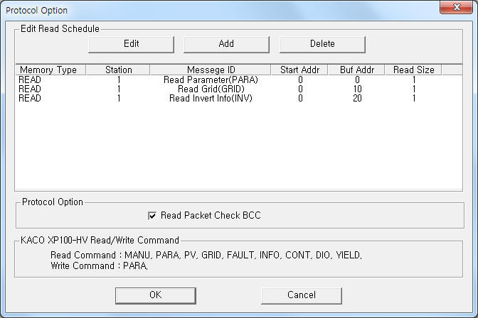
can see the dialogue box such as <Figure 2>. you can also set read schedule by
using this part.
in protocol option part, you
can see the dialogue box such as <Figure 2>. you can also set read schedule by
using this part.
 |
| <Figure 2> Example of KACO XP100-HV Inverter communication driver¡¯s Option dialogue box |
You can set read schedule by using ![]() ,
, ![]() ,
, ![]() button and listbox
of <Figure 2>.
button and listbox
of <Figure 2>.
Whether to use 'Check Sum' is set by using the part of ¡®Read Packet Check BCC¡¯ shown in <Figure 2>.
 |
| <Figure 3> Example of KACO XP100-HV Inverter communication driver¡¯s read schedule Add/Edit dialogue box |
When you click Add button or Edit button in dialogue box of <Figure 2>, dialogue box of <Figure 3> is shown.
You can write parameter setting by using write settings.
Bit Write
Bit write and word write have the same setting parameters except output value. ( 0 , 1 )
Word Write
Word write setting parameters are as follows:
1) PORT Port no. (0 ~ 255)
2) STATION Don't care.
3) ADDRESS Address of parameter = 0 ~ 99(decimal).
4) Extra1 Write command = PARA.
5) Extra2 Don't care.